
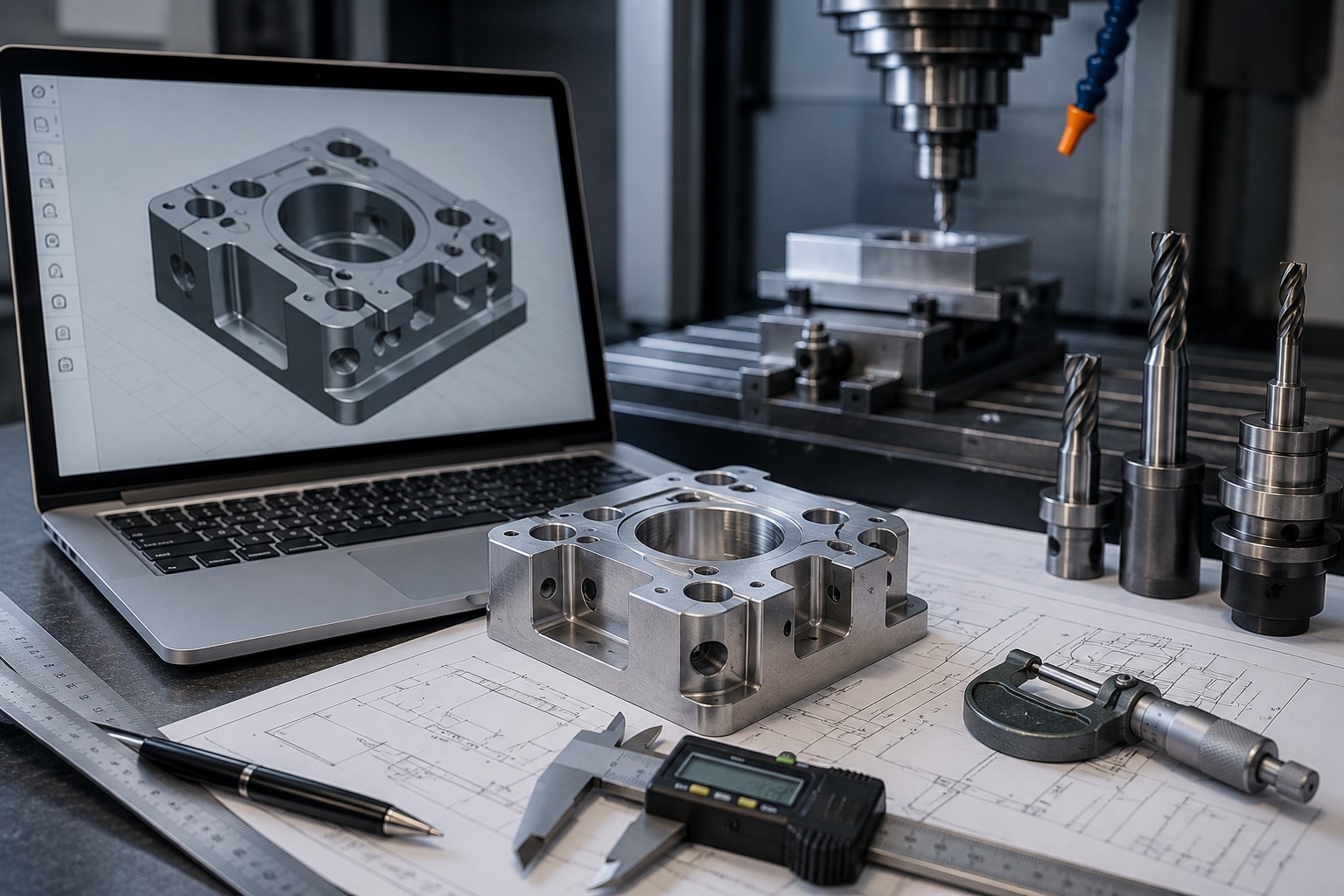
Design Smarter for Accurate, Cost-Effective CNC Machined Parts
A well-designed component can make CNC machining faster, more accurate, and more cost-effective. However, even a strong CAD model can create manufacturing challenges if it contains unnecessary tight tolerances, deep cavities, thin walls, or difficult-to-machine features.
Therefore, following practical CNC machining design guidelines during the product development stage can help manufacturers reduce machining time, improve part quality, and avoid unnecessary production costs.
At Polymach365, we support CNC milling, CNC turning, 3-axis, 4-axis, and 5-axis machining, prototype manufacturing, low-volume production, custom CNC parts, and precision components. By considering manufacturability before production, engineers can create designs that are easier to machine and more reliable in the final application.
What Is CNC Design for Manufacturing?
CNC design for manufacturing, often called DFM, means designing a component with the machining process in mind.
Instead of creating a part first and determining how to manufacture it later, engineers consider factors such as:
- Tool accessibility
- Material selection
- Part geometry
- Wall thickness
- Hole size
- Corner radius
- Machining tolerances
- Surface finish
- Workholding
- Production quantity
As a result, CNC-friendly designs can reduce manufacturing difficulties while maintaining the required functionality.
1. Avoid Unnecessarily Tight Tolerances
One of the most important CNC machining design guidelines is to specify tolerances according to actual functional requirements.
Not every feature requires extremely tight dimensional control.
For example, a critical bearing seat may require a tighter tolerance than a simple mounting surface.
Therefore, identify critical dimensions and apply tighter tolerances only where necessary.
This approach can help reduce:
- Machining time
- Inspection requirements
- Tooling costs
- Rework
- Production complexity
Consequently, designing for realistic tolerances can improve both manufacturing efficiency and overall project cost.
2. Choose Appropriate Wall Thickness
Thin walls can create machining challenges because cutting forces and heat can cause vibration or deformation.
Therefore, avoid unnecessarily thin sections whenever the application allows.
A stronger wall design can provide:
- Better rigidity
- Reduced vibration
- Improved dimensional stability
- Easier machining
- More consistent results
However, the ideal wall thickness depends on the material, geometry, machining process, and application.
Therefore, engineers should evaluate thin-wall features carefully before production.
3. Use Suitable Internal Corner Radii
CNC cutting tools are generally cylindrical. As a result, they naturally create rounded internal corners rather than perfectly sharp inside corners.
Therefore, designing internal corners with an appropriate radius can make machining easier.
Instead of specifying a sharp 90-degree internal corner, consider using a radius that matches an available cutting tool.
This can help:
- Reduce machining time
- Improve tool access
- Reduce tool wear
- Avoid unnecessary machining operations
- Improve surface quality
Furthermore, larger internal radii can often allow the use of larger and more rigid cutting tools.
4. Design Holes for Standard Cutting Tools
Holes are common CNC-machined features. However, unusual hole dimensions can increase tooling and machining requirements.
Therefore, use standard drill sizes whenever possible.
Standard holes can help manufacturers:
- Use readily available tooling
- Reduce setup time
- Improve production efficiency
- Simplify inspection
- Reduce machining costs
For precision holes, additional operations such as reaming or boring may be appropriate.
Consequently, hole design should consider both the required function and the available machining process.
5. Avoid Excessively Deep Cavities
Deep pockets and cavities can be difficult to machine because cutting tools may need to extend significantly into the workpiece.
Long tools can introduce:
- Tool deflection
- Vibration
- Reduced cutting stability
- Longer machining times
- Poorer surface finish
Therefore, keep pockets as shallow as practical.
If a deep cavity is necessary, discuss the geometry with your CNC machining provider before production.
A suitable tool diameter, machining strategy, or multi-axis process may provide a better solution.
6. Consider Tool Accessibility
A CNC machine can only cut a feature if the tool can physically reach it.
Therefore, tool accessibility should be considered during CAD design.
Features located inside deep pockets, narrow channels, or enclosed areas may require special tooling or additional setups.
Before finalizing a design, consider:
Can the cutting tool reach the feature?
If the answer is no, the geometry may require a different machining strategy.
Consequently, designing for tool access can reduce unnecessary setups and manufacturing complications.
7. Select the Right Material
Material selection has a direct effect on machining performance.
Common CNC machining materials include:
- Aluminum
- Stainless steel
- Carbon steel
- Tool steel
- Brass
- Copper
- Titanium
- ABS
- Nylon
- Delrin
- PEEK
- Polycarbonate
For example, aluminum is generally lightweight and machinable, while stainless steel provides strength and corrosion resistance.
Therefore, material selection should consider:
- Strength
- Weight
- Temperature resistance
- Corrosion resistance
- Wear resistance
- Machinability
- Application requirements
- Cost
Choosing a material that matches the application can improve both component performance and manufacturing efficiency.
8. Keep Designs Simple Where Possible
Complexity can increase machining time and production costs.
Therefore, avoid adding features that do not provide a functional benefit.
Simple designs can reduce:
- Number of setups
- Tool changes
- Programming time
- Machining operations
- Inspection requirements
However, complex geometries are sometimes necessary.
In these situations, 4-axis or 5-axis CNC machining can provide greater flexibility and access to multiple surfaces.
As a result, the goal is not to eliminate complexity but to use it only when the application requires it.
9. Plan the Workholding Strategy
Workholding keeps the component securely positioned during machining.
Therefore, the design should provide enough surface area for reliable fixturing.
Avoid placing critical features where clamps or fixtures could interfere with machining.
Furthermore, components that require machining on multiple sides may need additional setups.
Consequently, considering workholding during the design stage can improve machining stability and reduce repositioning time.
10. Consider Surface Finish Requirements
Not every surface requires the same finish.
Therefore, specify surface finish requirements only where they are functionally necessary.
For example, a sealing surface or bearing interface may require a smoother finish than a non-functional exterior surface.
Unnecessary surface-finish requirements can increase machining and finishing costs.
As a result, clearly identifying functional surfaces helps manufacturers select the appropriate machining and finishing process.
11. Design Threads Carefully
Threaded holes are common in CNC-machined components.
When designing threads, consider:
- Thread size
- Thread depth
- Hole diameter
- Tool accessibility
- Material
- Required strength
Avoid making threaded holes unnecessarily deep when the application does not require them.
Furthermore, provide sufficient space around threaded features for the cutting tool or threading tool.
Therefore, practical thread design can simplify machining and improve reliability.
12. Minimize the Number of Machining Setups
Every additional setup can increase production time and introduce opportunities for positioning errors.
Therefore, design components so that as many features as possible can be machined in fewer setups.
Multi-axis machining can help access multiple surfaces without repeatedly repositioning the component.
As a result, reducing setups can improve:
- Production efficiency
- Dimensional consistency
- Machining time
- Overall cost
CNC Milling Design Guidelines
CNC milling is suitable for brackets, housings, plates, fixtures, mold components, tooling, and complex mechanical parts.
When designing milled components:
- Use practical internal radii
- Avoid unnecessarily deep pockets
- Provide adequate wall thickness
- Consider tool access
- Use standard hole sizes
- Avoid unnecessary tight tolerances
- Plan workholding surfaces
Furthermore, consider whether 3-axis, 4-axis, or 5-axis machining is appropriate for the component.
CNC Turning Design Guidelines
CNC turning is commonly used for shafts, pins, bushings, sleeves, spacers, rollers, and other rotational components.
For turned parts:
- Use practical diameters
- Avoid unnecessarily long unsupported sections
- Consider tool access
- Specify critical diameters carefully
- Use appropriate thread dimensions
- Consider surface finish requirements
- Avoid unnecessary complex profiles
Therefore, a turning-friendly design can improve machining efficiency and dimensional consistency.
How Good CNC Design Reduces Manufacturing Costs
Good design does more than improve manufacturability. It can also reduce the total cost of production.
A CNC-friendly design can help reduce:
Programming Time → Setup Time → Tool Changes → Machining Time → Inspection → Rework
Therefore, DFM should be considered before production rather than after manufacturing problems occur.
For prototypes, this is particularly important because design changes made early are generally easier to implement than modifications made after production begins.
CNC Design for Prototypes and Production
A good CNC design should work not only for the first prototype but also for future production.
Therefore, engineers should consider:
- Prototype requirements
- Production quantity
- Material availability
- Machining process
- Inspection requirements
- Repeatability
- Future design changes
A design that is easy to prototype but difficult to manufacture in larger quantities may require redesign before production.
Consequently, designing with the complete product lifecycle in mind can make the transition from prototype to production smoother.
How Polymach365 Supports CNC Manufacturing
At Polymach365, customers can submit CAD designs for CNC manufacturing requirements.
Our capabilities include:
- CNC Milling
- CNC Turning
- 5-Axis CNC Machining
- Prototype Manufacturing
- Low-Volume Production
- Custom CNC Machining
- Precision Machined Components
- Mold Components
The manufacturing process can begin with your digital design and move toward production through a streamlined workflow.
Manufacturing Workflow
CAD File → Manufacturing Review → CNC Machining → Quality Inspection → Finished Parts
Therefore, providing accurate CAD files and clearly identifying materials, quantities, tolerances, and finishing requirements can help establish an appropriate manufacturing approach.
Following practical CNC machining design guidelines can significantly improve manufacturing results. By considering tolerances, wall thickness, corner radii, hole sizes, tool accessibility, material selection, workholding, and machining setups during the design stage, engineers can create parts that are easier and more economical to manufacture.
The objective is not simply to make a component that can be machined. Instead, the goal is to create a design that can be machined accurately, efficiently, consistently, and cost-effectively.
Whether you are developing a prototype, custom component, mold component, or production part, Polymach365 can support your CNC manufacturing requirements from digital design to finished components.
Have a CAD design ready?
Upload your CAD file and provide your material, quantity, tolerance, and finishing requirements to begin your CNC machining project with Polymach365.