A Practical Guide to Improving CNC Machined Part Quality
CNC machining delivers accurate and repeatable components for industries such as automotive, aerospace, medical, robotics, tooling, and industrial manufacturing. However, even advanced CNC equipment can produce defects when machining parameters, tooling, workholding, programming, or material conditions are not properly controlled.
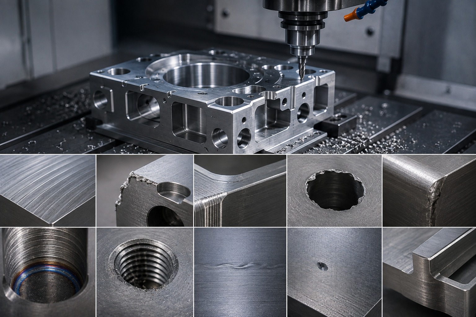
Common CNC machining defects can affect dimensional accuracy, surface finish, part geometry, assembly, and overall product performance. Therefore, identifying the cause of a defect early can help manufacturers reduce scrap, rework, production delays, and unnecessary costs.
At Polymach365, we provide CNC milling, CNC turning, 3-axis, 4-axis and 5-axis machining, prototype manufacturing, low-volume production, custom CNC parts, and precision machining solutions. Understanding common machining problems can help engineers design and manufacture better components.
What Are CNC Machining Defects?
CNC machining defects are unwanted variations or imperfections that occur during the manufacturing process.
They may result from:
- Incorrect cutting parameters
- Tool wear
- Improper workholding
- Machine vibration
- Material characteristics
- Programming errors
- Poor tool selection
- Excessive heat
- Incorrect tolerances
- Inadequate inspection
Therefore, CNC quality control requires manufacturers to consider the complete machining process rather than focusing only on the finished component.
1. Poor Surface Finish
Poor surface finish is one of the most common CNC machining defects.
A machined surface may show:
- Visible tool marks
- Roughness
- Scratches
- Chatter patterns
- Uneven surfaces
Common Causes
Poor surface finish can result from:
- Worn cutting tools
- Incorrect feed rate
- Incorrect spindle speed
- Excessive cutting depth
- Machine vibration
- Poor workholding
- Incorrect tool geometry
How to Prevent It
Manufacturers can improve surface finish by:
- Using sharp and suitable cutting tools
- Optimizing cutting parameters
- Reducing vibration
- Improving workholding
- Selecting the appropriate toolpath
- Using suitable finishing passes
Consequently, proper process control can produce smoother and more consistent machined surfaces.
2. Dimensional Inaccuracy
Dimensional errors occur when the finished component does not meet the specified dimensions.
For example, a hole may be too large, a shaft may be undersized, or a pocket may be deeper than required.
Common Causes
- Tool wear
- Machine calibration issues
- Thermal expansion
- Incorrect tool offsets
- Programming errors
- Material movement
- Improper workholding
How to Prevent It
Manufacturers can reduce dimensional errors by:
- Checking machine calibration
- Verifying tool offsets
- Monitoring tool wear
- Controlling machining temperature
- Inspecting critical dimensions
- Using appropriate cutting parameters
Therefore, regular measurement during production can help identify dimensional changes before they result in multiple defective parts.
3. Chatter and Vibration
Chatter appears as unwanted vibration between the cutting tool, machine, workpiece, or fixture.
It can produce visible marks and reduce surface quality.
Common Causes
- Excessive cutting speed
- Long tool overhang
- Weak workholding
- Incorrect cutting parameters
- Poor machine rigidity
- Large cutting forces
How to Prevent CNC Chatter
Manufacturers can reduce chatter by:
- Shortening tool overhang
- Improving workholding
- Adjusting spindle speed
- Reducing cutting depth
- Using appropriate tooling
- Optimizing toolpaths
Furthermore, selecting a more rigid setup can significantly improve machining stability.
4. Tool Wear
Cutting tools gradually wear as they remove material.
As tool wear increases, manufacturers may experience:
- Dimensional variation
- Poor surface finish
- Increased cutting forces
- Higher temperatures
- Tool breakage
- Reduced productivity
How to Prevent Tool Wear
Manufacturers should:
- Select the correct cutting tool
- Use appropriate cutting parameters
- Monitor tool condition
- Use suitable coolant or lubrication when required
- Replace tools at appropriate intervals
Therefore, proactive tool monitoring can help maintain consistent part quality.
5. Burr Formation
Burrs are small unwanted pieces of material that remain along machined edges.
They commonly occur around:
- Holes
- Slots
- External edges
- Intersections
- Milled pockets
Common Causes
Burr formation can be influenced by:
- Tool condition
- Cutting direction
- Material properties
- Cutting parameters
- Tool geometry
How to Prevent Burrs
Manufacturers can reduce burrs through:
- Proper tool selection
- Optimized cutting conditions
- Appropriate cutting direction
- Edge-break specifications
- Deburring operations
Consequently, including practical edge-break requirements in the design can simplify finishing.
6. Tool Breakage
Tool breakage can cause serious production problems.
A broken cutting tool can damage the workpiece, interrupt production, and potentially affect the machine.
Common Causes
- Excessive cutting forces
- Incorrect feeds and speeds
- Excessive tool engagement
- Long tool overhang
- Poor workholding
- Incorrect tool selection
- Hard or difficult-to-machine materials
Prevention
To reduce tool breakage:
- Use appropriate tooling
- Optimize cutting parameters
- Minimize tool overhang
- Maintain secure workholding
- Monitor cutting conditions
- Use suitable machining strategies
Therefore, matching the tool to the material and geometry is essential.
7. Thermal Deformation
Heat is generated during CNC machining, particularly during aggressive cutting operations.
Excessive heat can cause the workpiece or machine components to expand.
As a result, the component may move outside the required dimensional tolerance.
How to Prevent Thermal Problems
Manufacturers can:
- Control cutting parameters
- Use appropriate coolant
- Allow suitable cooling time
- Monitor machining temperatures
- Avoid unnecessarily aggressive cutting
This becomes especially important when manufacturing components with tight tolerances.
8. Incorrect Hole Dimensions or Positions
Holes are critical features in many CNC machined components.
Problems may include:
- Incorrect hole diameter
- Incorrect hole depth
- Misaligned holes
- Incorrect hole position
- Poor surface quality
Common Causes
- Incorrect tool selection
- Tool deflection
- Machine positioning errors
- Improper workholding
- Tool wear
- Programming mistakes
Prevention
Manufacturers can improve hole accuracy by:
- Using suitable drilling tools
- Checking tool offsets
- Using reaming or boring when required
- Verifying hole locations
- Inspecting critical features
Therefore, hole requirements should be clearly specified in the CAD model or engineering drawing.
9. Warping and Part Deformation
Thin or flexible components can deform during machining.
This is particularly important when machining:
- Thin walls
- Long components
- Thin plates
- Flexible materials
- Components with uneven material removal
Common Causes
- Excessive cutting forces
- Poor workholding
- Internal material stresses
- Excessive heat
- Improper machining sequence
How to Prevent Deformation
Manufacturers can:
- Improve workholding
- Use lighter cutting passes
- Optimize machining sequences
- Maintain adequate wall thickness
- Remove material gradually
Consequently, proper part design and machining strategy can reduce deformation.
10. Incorrect Surface Geometry
Sometimes a component may meet its basic dimensions but still have problems with flatness, parallelism, perpendicularity, or other geometric characteristics.
For example, two surfaces may have the correct dimensions but fail to remain parallel.
Common Causes
- Poor machine setup
- Workpiece movement
- Tool deflection
- Thermal effects
- Incorrect machining sequence
- Inadequate inspection
Prevention
Manufacturers can improve geometric accuracy by:
- Establishing reliable datums
- Improving workholding
- Using appropriate machining sequences
- Checking critical geometric features
- Performing in-process inspection
Therefore, geometric tolerances should be considered alongside dimensional tolerances.
11. Incorrect Toolpath or Programming Errors
CNC machines depend on programmed toolpaths.
A programming error can result in:
- Incorrect dimensions
- Unexpected tool movement
- Incorrect feature locations
- Surface defects
- Tool collisions
- Scrap parts
How to Prevent Programming Errors
Before machining, manufacturers should:
- Verify the CAD model
- Simulate toolpaths
- Check cutting directions
- Confirm tool offsets
- Verify work coordinates
- Perform appropriate program testing
As a result, digital verification can reduce the risk of programming-related defects.
12. Poor Workholding
A workpiece must remain securely positioned throughout machining.
If the component moves or vibrates, dimensional accuracy and surface quality can suffer.
Common Problems
- Part movement
- Vibration
- Incorrect positioning
- Distortion from excessive clamping force
How to Prevent Workholding Problems
Manufacturers should:
- Use suitable fixtures
- Apply appropriate clamping force
- Support thin sections
- Ensure proper fixture alignment
- Provide sufficient contact surfaces
Therefore, workholding should be considered during both part design and manufacturing planning.
How to Reduce CNC Machining Defects
Preventing defects requires a systematic manufacturing approach.
1. Start with a Manufacturable Design
Consider tool access, tolerances, wall thickness, internal radii, hole sizes, and workholding before production.
2. Select the Correct Material
Choose materials based on strength, machinability, temperature, corrosion, and application requirements.
3. Use Appropriate Cutting Tools
Tool geometry and material should match the workpiece and machining operation.
4. Optimize Cutting Parameters
Feeds, speeds, depth of cut, and tool engagement should be selected according to the material and machining process.
5. Monitor Tool Wear
Replace worn tools before they begin affecting component quality.
6. Maintain CNC Equipment
Regular maintenance and calibration help maintain machine performance.
7. Inspect Critical Features
Use appropriate measurement equipment to verify important dimensions and geometries.
Consequently, combining good design, process control, tooling, and inspection can significantly reduce CNC machining defects.
CNC Machining Quality Control at Polymach365
Quality starts before the CNC machine begins cutting.
At Polymach365, the manufacturing workflow begins with the digital design and considers the machining requirements before production.
Our capabilities include:
- CNC Milling
- CNC Turning
- 5-Axis CNC Machining
- Prototype Manufacturing
- Low-Volume Production
- Custom CNC Machining
- Precision Machined Components
- Mold Components
Manufacturing Workflow
CAD File → Manufacturing Review → CNC Machining → Quality Inspection → Finished Components
Therefore, clearly providing your material, quantity, tolerances, surface finish, and other technical requirements can help establish an appropriate manufacturing approach.
Common CNC machining defects such as poor surface finish, dimensional inaccuracies, chatter, tool wear, burrs, tool breakage, thermal deformation, hole errors, warping, and programming problems can affect the quality and performance of finished components.
However, many of these problems can be prevented through proper design, appropriate tooling, optimized machining parameters, secure workholding, machine maintenance, and effective inspection.
Therefore, manufacturers should treat CNC quality control as an entire process rather than simply checking the finished part.
Whether you need a CNC prototype, custom machined component, mold component, low-volume production run, or production part, Polymach365 can support your manufacturing requirements with CNC milling, CNC turning, multi-axis machining, and digital manufacturing solutions.
Have a CAD design ready?
Upload your CAD file and provide your material, quantity, tolerance, and finishing requirements to start your CNC machining project with Polymach365.