A Complete Guide to the CNC Machining Process
CNC machining is one of the most widely used manufacturing methods for producing accurate metal and plastic components. From prototypes and custom parts to low-volume production and complex industrial components, CNC machining can transform a digital design into a precise physical part.
But how does CNC machining actually work?
The process involves several stages, starting with a CAD model and ending with an inspected, finished component. Each stage affects the accuracy, quality, cost, and production time of the final part.
At Polymach365, we support CNC milling, CNC turning, 3-axis, 4-axis, and 5-axis machining, prototype manufacturing, low-volume production, custom CNC components, and precision machined parts.
What Is CNC Machining?
CNC stands for Computer Numerical Control. CNC machining uses computer-controlled equipment to remove material from a workpiece according to programmed instructions.
Instead of manually controlling the cutting tool, the machine follows a digital program that controls movements along different axes.
Depending on the machine, CNC equipment can perform operations such as:
- Milling
- Turning
- Drilling
- Boring
- Threading
- Tapping
- Reaming
- Contouring
- Pocketing
Therefore, CNC machining can produce components with accurate dimensions and repeatable features.
How Does CNC Machining Work?
A typical CNC manufacturing process follows this sequence:
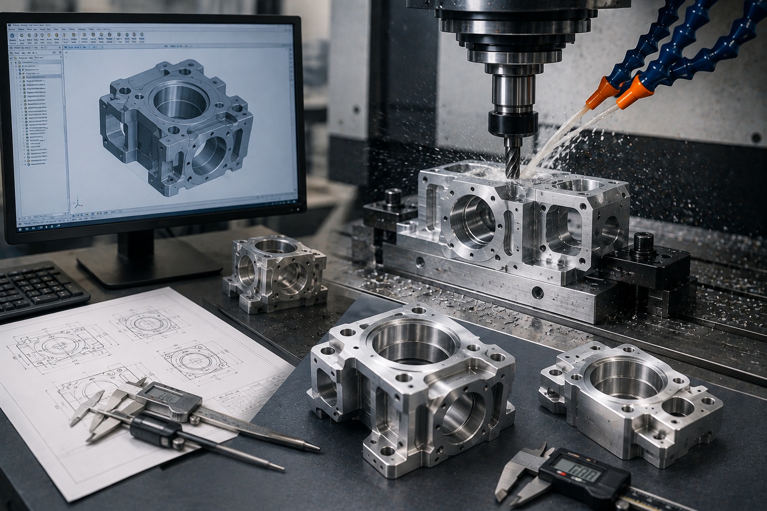
CAD Design → Design Review → CAM Programming → Machine Setup → Material Preparation → CNC Machining → Inspection → Finishing → Finished Part
Each stage has an important role in producing the final component.
1. Create the CAD Design
The CNC machining process begins with a Computer-Aided Design (CAD) model.
Engineers use CAD software to create a detailed representation of the component. The model defines the geometry and dimensions required for manufacturing.
A CAD design may include:
- Overall dimensions
- Holes
- Slots
- Pockets
- Threads
- Curves
- Contours
- Internal features
- Mounting locations
Engineering drawings may also provide information about:
- Tolerances
- Surface finishes
- Materials
- Critical dimensions
Therefore, an accurate CAD model provides the foundation for the entire machining process.
2. Review the Design for Manufacturability
Before production begins, the design should be reviewed to determine whether it can be manufactured efficiently.
This stage is often referred to as Design for Manufacturability (DFM).
Manufacturers may evaluate:
- Tool accessibility
- Internal corner radii
- Wall thickness
- Hole sizes
- Deep cavities
- Tight tolerances
- Workholding requirements
- Material selection
For example, a very deep pocket may require a long cutting tool, which can increase vibration and reduce machining efficiency.
Therefore, identifying potential manufacturing problems before machining can reduce unnecessary production delays and costs.
3. Convert the CAD Model into a CAM Program
The CAD model describes what the part should look like. However, the CNC machine needs specific instructions explaining how to manufacture it.
This is where Computer-Aided Manufacturing (CAM) software is used.
CAM software generates toolpaths that determine how the cutting tool will move.
The program can define:
- Tool movements
- Cutting directions
- Spindle speeds
- Feed rates
- Cutting depths
- Tool changes
- Machining sequences
The resulting instructions are then converted into machine-readable CNC code.
Consequently, CAM programming connects the digital design with the physical machining process.
4. Select the CNC Machine
The appropriate CNC machine depends on the component’s geometry and manufacturing requirements.
Common CNC machines include:
3-Axis CNC Machines
These machines move the cutting tool along three primary axes.
They are suitable for many straightforward components such as:
- Plates
- Brackets
- Housings
- Fixtures
- Mounting components
4-Axis CNC Machines
A fourth axis allows additional rotational movement.
Therefore, 4-axis machining can provide greater access to multiple surfaces.
5-Axis CNC Machines
5-axis machines can move the tool and workpiece across multiple axes.
They are particularly useful for:
- Complex contours
- Angled surfaces
- Multi-sided components
- Deep features
- Complex tooling
CNC Lathes
CNC turning machines rotate the workpiece while cutting tools remove material.
They are commonly used for:
- Shafts
- Pins
- Bushings
- Sleeves
- Rollers
- Spacers
Therefore, selecting the right CNC machine is essential for efficient production.
5. Select the Material
The next step is preparing the correct workpiece material.
CNC machining can process many metals and engineering plastics.
Common materials include:
- Aluminum
- Stainless steel
- Carbon steel
- Tool steel
- Brass
- Copper
- Titanium
- ABS
- Nylon
- Delrin
- Polycarbonate
- PEEK
Material selection depends on the component’s:
- Strength requirements
- Weight
- Temperature exposure
- Corrosion resistance
- Wear resistance
- Electrical properties
- Cost
- Application
Therefore, material selection should be considered during the design stage rather than after the CAD model is completed.
6. Secure the Workpiece
Before machining begins, the material must be securely positioned in the CNC machine.
This process is known as workholding.
Common workholding methods include:
- Vises
- Clamps
- Fixtures
- Chucks
- Custom workholding systems
The workpiece must remain stable during cutting.
Poor workholding can cause:
- Vibration
- Part movement
- Dimensional errors
- Surface defects
- Component deformation
Therefore, proper workholding is essential for maintaining machining accuracy.
7. Install and Set Up Cutting Tools
Different machining operations require different cutting tools.
Common CNC tools include:
- End mills
- Drills
- Ball-nose cutters
- Reamers
- Taps
- Boring tools
- Face mills
The manufacturer selects tooling according to the material, geometry, feature size, and machining operation.
For example, an end mill may be used for pockets and contours, while a drill can create holes.
Consequently, correct tool selection affects machining efficiency, tool life, surface finish, and dimensional accuracy.
8. CNC Machine Removes Material
Once the machine is set up, the CNC program controls the machining operation.
The cutting tool removes material according to the programmed toolpath.
Depending on the component, machining may involve:
Roughing
Roughing removes larger amounts of material quickly.
Semi-Finishing
Semi-finishing brings the component closer to its final dimensions.
Finishing
Finishing operations remove smaller amounts of material to achieve the required dimensions and surface quality.
Therefore, complex components may require multiple machining operations before they reach their final form.
9. Monitor the Machining Process
CNC machining is automated, but monitoring remains important.
Manufacturers may monitor:
- Tool wear
- Cutting conditions
- Machine vibration
- Coolant flow
- Material behavior
- Dimensional changes
Tool wear can gradually affect component dimensions and surface finish.
Therefore, monitoring tool condition is particularly important during longer production runs.
10. Inspect the Finished Component
After machining, the finished component is inspected against the applicable specifications.
Inspection may include:
- Overall dimensions
- Hole diameters
- Hole positions
- Thickness
- Flatness
- Surface finish
- Geometric tolerances
Depending on the component, manufacturers may use equipment such as:
- Calipers
- Micrometers
- Height gauges
- Bore gauges
- Coordinate Measuring Machines (CMM)
Therefore, inspection helps confirm that the finished component meets the required specifications.
11. Apply Finishing Processes
Some CNC machined components require additional finishing after machining.
Possible finishing processes include:
- Deburring
- Polishing
- Anodizing
- Powder coating
- Plating
- Heat treatment
The appropriate finishing method depends on the component’s material and application.
For example, a component may require a protective coating to improve corrosion resistance or a specific surface treatment for appearance.
Consequently, finishing can improve both functional and aesthetic properties.
CNC Milling vs CNC Turning
CNC machining includes several different manufacturing processes.
CNC Milling
In CNC milling, the cutting tool rotates while the workpiece is secured in position.
Milling is suitable for components with:
- Pockets
- Slots
- Holes
- Flat surfaces
- Complex contours
CNC Turning
In CNC turning, the workpiece rotates while the cutting tool removes material.
Turning is suitable for:
- Shafts
- Pins
- Bushings
- Sleeves
- Cylindrical components
Therefore, the component’s geometry determines whether milling, turning, or a combination of processes is most appropriate.
CNC Machining for Prototypes
CNC machining is commonly used to manufacture functional prototypes.
Instead of producing only a visual model, engineers can manufacture a prototype from metal or engineering plastic.
This allows teams to test:
- Fit
- Function
- Assembly
- Dimensions
- Strength
- Surface finish
A typical development process is:
CAD Design → DFM Review → CNC Prototype → Testing → Design Improvements → Production
As a result, CNC machining can help identify design problems before larger production quantities are manufactured.
CNC Machining for Low-Volume Production
CNC machining is also suitable for small production quantities.
Businesses may require low-volume components for:
- Product validation
- Specialized equipment
- Replacement parts
- Pilot production
- Engineering changes
- Custom machinery
Therefore, CNC machining can provide flexibility when large production volumes are unnecessary.
CNC Machining for Complex Parts
Complex components may require advanced machining capabilities.
5-axis CNC machining can provide access to multiple surfaces and difficult-to-reach features.
This can be useful for:
- Aerospace components
- Complex tooling
- Industrial components
- Robotics parts
- Mold components
- Specialized mechanical parts
Consequently, choosing the correct machining technology can improve manufacturing efficiency for complex designs.
Factors That Affect CNC Machining Results
The final quality of a CNC machined component depends on several factors.
These include:
- Machine capability
- Tool condition
- Material
- Cutting parameters
- Workholding
- Part geometry
- Machine calibration
- Temperature
- Programming
- Inspection
Therefore, successful CNC manufacturing requires control over the complete process rather than relying on the machine alone.
How Polymach365 Supports CNC Manufacturing
At Polymach365, we provide digital manufacturing solutions that connect CAD designs with CNC production.
Our capabilities include:
- CNC Milling
- CNC Turning
- 3-Axis CNC Machining
- 4-Axis CNC Machining
- 5-Axis CNC Machining
- Prototype Manufacturing
- Low-Volume Production
- Custom CNC Machining
- Precision Machined Components
- Mold Components
Our Digital Manufacturing Workflow
Upload CAD File → Manufacturing Review → Quote → CNC Machining → Quality Inspection → Finished Part
Therefore, customers can provide their CAD model along with material, quantity, tolerance, and finishing requirements to begin the manufacturing process.
Benefits of CNC Machining
CNC machining offers several advantages for modern manufacturing.
High Repeatability
Computer-controlled machining can reproduce the same programmed operations across multiple components.
Design Flexibility
CNC machines can manufacture a wide range of geometries.
Material Variety
Manufacturers can work with numerous metals and engineering plastics.
Prototype-Friendly
CNC machining can produce functional prototypes directly from digital designs.
Low-Volume Capability
Manufacturers can produce small quantities without necessarily requiring dedicated high-volume tooling.
Complex Geometry
Multi-axis CNC machining can support challenging component designs.
Production Scalability
The same digital manufacturing approach can support prototypes and production components.
As a result, CNC machining remains an important manufacturing method for modern product development.
Final Thoughts
CNC machining transforms a digital CAD design into a physical component through a series of controlled manufacturing steps.
The process begins with CAD design and continues through DFM review, CAM programming, machine setup, material preparation, CNC machining, inspection, and finishing.
Each stage contributes to the final quality of the component. Therefore, careful design, appropriate material selection, suitable tooling, accurate programming, secure workholding, and effective inspection are essential for reliable CNC manufacturing.
Whether you need a prototype, custom metal part, replacement component, mold component, low-volume batch, or production part, Polymach365 can support your project with CNC milling, CNC turning, multi-axis machining, and digital manufacturing solutions.
Start Your CNC Machining Project
Have a CAD design ready?
Upload your CAD file and provide your material, quantity, tolerances, and finishing requirements to start your CNC machining project with Polymach365.