Introduction
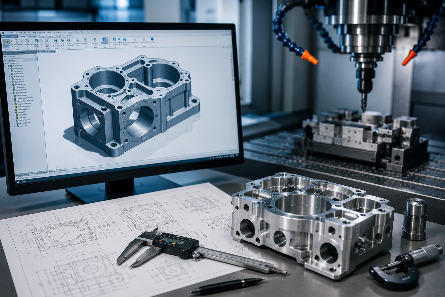
Computer-Aided Design (CAD) plays a critical role in modern CNC manufacturing. Before a CNC machine begins cutting material, manufacturers need accurate digital information that defines the part’s geometry, dimensions, tolerances, holes, features, and other manufacturing requirements .
A well-prepared CAD design helps manufacturers understand exactly what needs to be produced. Furthermore, it can reduce design errors, improve machining accuracy, simplify production planning, and support better quality control.
At Polymach365 , digital manufacturing connects CAD designs with CNC machining processes, including CNC milling, CNC turning, 3-axis, 4-axis, and 5-axis machining, prototype manufacturing, low-volume production, and custom machined parts.
What Is CAD in CNC Manufacturing?
CAD stands for Computer-Aided Design . It is used to create detailed digital models of components before they are manufactured.
A CAD model can define important information such as:
- Part dimensions
- Geometry
- Holes and slots
- Curves and contours
- Wall thickness
- Internal features
- Mounting locations
- Critical surfaces
- Design intent
Therefore, CAD provides the digital foundation for CNC manufacturing.
Instead of relying only on sketches or manually interpreted drawings, manufacturers can use the digital model to prepare the machining process.
How CAD Connects With CNC Machining
The CNC manufacturing process typically begins with a digital design.
A simplified workflow is:
CAD Design → DFM Review → CAM Programming → CNC Machining → Inspection → Finished Part
First, the engineer creates the component in CAD software. Next, the design can be reviewed for manufacturing ability.
Then, CAM software can use the design information to create machining toolpaths. These toolpaths guide the CNC machine during cutting.
As a result, accurate CAD data helps create a more reliable connection between design intent and physical production .
1. CAD Improves Machining Accuracy
Accurate machining starts with accurate design information.
A detailed CAD model defines the intended geometry of the component. Therefore, machinists and manufacturing engineers can work from a consistent digital reference.
CAD helps to communicate:
- Overall dimensions
- Feature locations
- Hole positions
- Contours
- Depths
- Angles
- Critical surfaces
Consequently, a properly prepared CAD model can reduce misunderstandings during manufacturing.
2. CAD Helps Identify Design Problems Early
Finding a manufacturing problem after production can begin resulting in wasted material, time, and money.
Therefore, reviewing the CAD model before machining is important.
Manufacturers can evaluate potential issues such as:
- Extremely thin walls
- Deep cavities
- Difficult tool access
- Small internal radii
- Unnecessary features
- Complex geometries
- Tight tolerances
As a result, engineers can make improvements before the part reaches the CNC machine.
3. CAD Supports Design for Manufactureability
CAD and Design for Manufacture (DFM) work closely together.
A component may function correctly in theory but still be difficult or expensive to machine.
For example, a design may contain a deep narrow pocket that requires a long cutting tool. Therefore, the engineer may modify the geometry to improve tool accessibility.
Similarly, unnecessarily tight tolerances can increase machining and inspection requirements.
Consequently, CAD provides an excellent environment for identifying and improving these issues before production.
4. CAD Makes Complex Parts Easier to Manufacture
Modern CNC machines can manufacture highly complex components.
However, complex geometry requires accurate digital information.
CAD models can represent:
- 3D contours
- Angled surfaces
- Curved profiles
- Deep pockets
- Multi-sided features
- Complex cavities
- Organic shapes
Therefore, CAD is particularly important when manufacturing components that require 4-axis or 5-axis CNC machining .
With an accurate model, manufacturers can develop suitable machining strategies for complex surfaces and features.
5. CAD Helps With CNC Milling
CNC milling is commonly used for components containing:
- Pockets
- Slots
- Holes
- Flat surfaces
- Contours
- Mounting features
- Complex profiles
A CAD model provides the geometry needed to create the appropriate milling toolpaths.
Therefore, the quality of the CAD model can directly affect machining preparation.
For example, missing or incorrect dimensions may result in additional clarification or design revisions before manufacturing can begin.
6. CAD Helps With CNC Turning
CAD is equally valuable for CNC turning.
Turning is commonly used to manufacture:
- Shafts
- Pins
- Bushings
- Sleeves
- Spacers
- Rollers
- Threaded components
The CAD model can define diameters, lengths, grooves, threads, shoulders, and other rotational features.
Consequently, accurate CAD information helps manufacturers prepare the turning process according to the required component geometry.
7. CAD Helps Control Tolerances
Not every dimension requires the same level of precision.
A CAD design can identify important dimensions and tolerances that affect component performance.
Critical features may include:
- Bearing fits
- Mating surfaces
- Hole locations
- Shaft diameters
- Sealing surfaces
- Alignment features
Therefore, engineers should specify tight tolerances only where they are functionally necessary.
This approach can help balance performance, manufacturing ability, and cost .
8. CAD Supports Prototype Manufacturing
Prototype development often involves several design changes.
A typical process is:
Initial CAD → Prototype → Testing → Design Changes → Revised CAD → New Prototype
Therefore, CAD makes it easier to modify the design and manufacture updated versions.
CNC machining can then produce functional prototypes from metals and engineering plastics.
As a result, engineers can evaluate fit, assembly, dimensions, and functionality before moving into production.
9. CAD Reduces Manufacturing Errors
Clear digital design information can reduce communication problems between engineers and manufacturers.
A good CAD package can provide a consistent reference for:
- Geometry
- Dimensions
- Features
- Manufacturing requirements
- Design revisions
Therefore, version control is also important.
Manufacturers should work from the approved and current CAD version to avoid producing outdated designs.
10. CAD Supports Faster Production Planning
Manufacturers need to understand the component before deciding how to machine it.
The CAD model helps them evaluate:
- Machine requirements
- Tool accessibility
- Workholding
- Number of setups
- Machining orientation
- Cutting strategy
- Material removal
Consequently, a well-prepared CAD model can simplify production planning.
This is particularly valuable for custom parts and complex CNC components.
CAD File Formats for CNC Machining
Different manufacturing platforms and CNC workflows may support different CAD formats.
Common formats include:
- STEP
- STP
- IGES
- IGS
- STL
- SLDPRT
Among these, STEP files are widely used for exchanging 3D CAD data between different software systems.
However, the preferred format depends on the manufacturing workflow and required information.
Therefore, it is important to provide the correct file format when requesting a CNC machining quote.
What Should a CAD File Include?
Before sending a CAD design for CNC manufacturing, check that it contains the necessary information.
Important details may include:
Part Geometry
The 3D model should accurately represent the intended component.
Dimensions
Critical dimensions should be clearly defined.
Tolerances
Specify tolerances where they are functionally necessary.
Material
Identify the required material.
Surface Finish
Mention required surface finish or finishing operations.
Quantity
State how many parts you need.
Additional Requirements
Includes threading, coating, anodizing, heat treatment, or other specifications where applicable.
Therefore, providing complete manufacturing information can help reduce delays during the quotation and production process.
CAD and CNC Machining Costs
CAD design can also influence manufacturing cost.
A complex design may require:
- More machining time
- Additional setups
- Specialized tooling
- Multi-axis machining
- Additional inspection
Therefore, optimizing the CAD model can sometimes reduce production costs.
For example, removing a non-functional feature or using a more practical internal radius may simplify machining.
However, design changes should never compromise the component’s required performance.
CAD for Low-Volume and Production Manufacturing
CAD is valuable for both low-volume and larger production projects.
For low-volume manufacturing, the digital model provides a repeatable reference for producing small batches.
For production manufacturing, the same approved CAD design can support repeated manufacturing runs.
Consequently, CAD helps create continuity from:
Prototype → Low-Volume Production → Production Manufacturing
This makes digital design an important part of the complete product development cycle.
Common CAD Design Mistakes to Avoid
Several CAD-related problems can create manufacturing difficulties.
Missing Dimensions
Important dimensions may require additional clarification.
Unnecessary Tight Tolerances
These can increase machining and inspection costs.
Poor Tool Accessibility
Some features may be difficult or impossible to reach with standard tools.
Extremely Deep Cavities
Deep features can require specialized tooling.
Very Small Internal Radii
These may require smaller cutting tools and longer machining times.
Outdated CAD Files
Manufacturing from an old revision can result in incorrect components.
Therefore, reviewing the design before submission can prevent many avoidable manufacturing issues.
CAD and Quality Control
CAD does not stop being useful after machining begins.
The digital model can also support inspection and quality control.
Finished components may be checked against the required:
- Dimensions
- Feature locations
- Tolerances
- Surface requirements
- Geometric specifications
Therefore, the CAD model can remain an important reference throughout the manufacturing process.
Why CAD Matters at Polymach365
At Polymach365 , CAD is an important part of our digital manufacturing workflow.
Our CNC manufacturing capabilities include:
- CNC Milling
- CNC Turning
- 3-Axis CNC Machining
- 4-Axis CNC Machining
- 5-Axis CNC Machining
- Prototype Machining
- Low-Volume Production
- Custom CNC Machining
- Precision Machined Components
- Mold Components
Our manufacturing workflow can be summarized as:
Upload CAD File → Manufacturing Review → Quote → CNC Machining → Quality Inspection → Delivery
Therefore, customers can start with their digital design and move toward a physical component through a streamlined manufacturing process.
How to Prepare Your CAD Design for CNC Machining
Before submitting your design, follow these steps:
1. Check the Geometry
Make sure the 3D model represents the intended component.
2. Review Critical Dimensions
Identify the dimensions that directly affect functionality.
3. Apply Practical Tolerances
Use tighter tolerances only where required.
4. Check Tool Accessibility
Make sure cutting tools can reach the required features.
5. Review Internal Radii
Use practical radii wherever possible.
6. Specify Material
Choose the material based on performance and manufacturing ability.
7. Specify Surface Finish
Identify any required finishing operations.
8. Confirm the File Version
Send the latest approved CAD model.
As a result, your design will be better prepared for the manufacturing process.
Final Thoughts
CAD design is the foundation of modern CNC manufacturing. It provides the digital information manufacturers need to understand, program, machine, and inspect a component.
A well-prepared CAD model can improve communication, support DFM, simplify machining, reduce errors, improve quality, and potentially lower production costs.
More importantly, CAD supports the entire manufacturing journey—from the initial concept and prototype to low-volume production and repeat manufacturing.
Therefore, before sending a component for CNC machining, take time to review its geometry, tolerances, material, surface finish, tool accessibility, and manufacturing requirements .
With the right CAD design and an appropriate CNC machining strategy, manufacturers can create a smoother and more efficient path from digital concept to finished part .
Start Your CNC Manufacturing Project
Do you have a CAD file ready?
Upload your design and provide the material, quantity, tolerances, surface finish, and other requirements to begin your CNC machining project with Polymach365.