
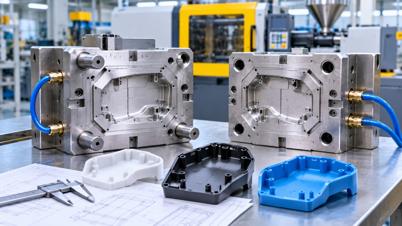
Common Injection Mold Design Problems and How to Avoid Them
Injection molding is an effective manufacturing process for producing plastic components with consistent shapes, dimensions, and surface finishes. However, even a well-planned production process can experience defects when the injection mold is not designed correctly.
Common injection mold design problems include sink marks, warping, short shots, flash, weld lines, air traps, and uneven cooling. These issues can affect product appearance, dimensional accuracy, component strength, and production efficiency.
Understanding these problems during the design stage helps manufacturers reduce defects, avoid unnecessary rework, and achieve better part quality. Here are some common injection mold design problems and practical ways to prevent them.
1. Sink Marks Caused by Uneven Wall Thickness
Sink marks are small depressions that appear on the surface of molded plastic components. They commonly develop when thicker sections cool and shrink more slowly than surrounding areas.
Common causes:
Uneven wall thickness
Excessively thick ribs and bosses
Insufficient packing pressure
Inadequate cooling time
How to avoid them:
Maintain uniform wall thickness throughout the component wherever possible. Design ribs and bosses with suitable dimensions to prevent excessive material accumulation. In addition, optimise packing pressure and cooling conditions to support uniform shrinkage.
2. Warping Due to Uneven Cooling
Warping occurs when a molded component bends, twists, or changes shape after cooling. This problem often results from uneven shrinkage across different sections of the part.
Common causes:
Uneven cooling channel placement
Inconsistent wall thickness
Different cooling rates across the component
Incorrect processing conditions
How to avoid it:
Design balanced cooling channels to maintain consistent mold temperatures. Avoid sudden changes in wall thickness and evaluate the component geometry before manufacturing. Mold flow analysis can also help identify areas where uneven cooling may cause deformation.
3. Short Shots Due to Poor Material Flow
A short shot occurs when molten plastic does not completely fill the mold cavity. As a result, the finished component may have missing sections or incomplete features.
Common causes:
Poor gate positioning
Narrow or restrictive flow channels
Insufficient injection pressure
Low material temperature
Thin sections that restrict plastic flow
How to avoid them:
Position gates to support effective material distribution throughout the cavity. Review runner dimensions and wall thickness to reduce flow restrictions. Engineers should also evaluate material flow and processing requirements before finalising the mold design.
4. Flash Caused by Improper Mold Closure
Flash is excess plastic material that escapes through the parting line or other gaps in the mold. It appears as thin unwanted material along the edges of the finished component.
Common causes:
Poor mold alignment
Incorrect parting line design
Insufficient clamping force
Damaged or worn mold surfaces
Excessive injection pressure
How to avoid it:
Ensure accurate alignment between the mold halves and design suitable parting surfaces. Proper mold construction and maintenance also help prevent gaps that allow molten plastic to escape.
5. Weld Lines Caused by Meeting Material Flows
Weld lines form when two or more streams of molten plastic meet inside the mold cavity but do not bond properly. These lines may appear as visible marks and can sometimes reduce local component strength.
Common causes:
Poor gate location
Complex component geometry
Low melt temperature
Inadequate material flow
Poor venting near the meeting point
How to avoid them:
Optimise gate locations to control how molten plastic enters the cavity. Review the flow path and adjust the design to reduce unnecessary flow separation. Suitable melt temperature and venting arrangements can also improve material bonding.
6. Air Traps Caused by Poor Mold Venting
Air traps occur when air becomes trapped inside the mold cavity as molten plastic enters. Compressed air can prevent complete filling or create burn marks and surface defects.
Common causes:
Insufficient venting
Poor gate placement
Complex cavity geometry
Incorrect filling patterns
How to avoid them:
Include suitable venting locations in the mold design, particularly near areas where air is likely to become trapped. Mold flow analysis can help identify potential air-trap locations and improve the filling sequence.
7. Ejection Problems and Part Sticking
Molded components sometimes stick to the core or cavity during ejection. This can cause scratches, deformation, cracks, or damage to delicate features.
Common causes:
Insufficient draft angles
Poor ejector pin placement
Deep vertical walls
Surface friction
Incorrect ejection system design
How to avoid them:
Include suitable draft angles on vertical surfaces to support smooth part removal. Position ejector pins in appropriate locations and distribute ejection forces evenly. For complex components, engineers may also consider sliders, lifters, or other specialised ejection mechanisms.
8. Uneven Cooling and Longer Production Cycles
Poor cooling channel design can increase cycle times and create inconsistent component quality. Some areas may solidify faster than others, resulting in dimensional variation and residual stress.
Common causes:
Incorrect cooling channel placement
Insufficient cooling coverage
Poor temperature distribution
Inadequate cooling system design
How to avoid them:
Plan cooling channels according to the component geometry and material requirements. Maintain balanced cooling around thicker sections and critical features. Simulation tools can help engineers evaluate temperature distribution before manufacturing the mold.
9. Dimensional Inaccuracy Due to Incorrect Shrinkage Allowance
Plastic materials shrink as they cool and solidify. If the mold dimensions do not account for material shrinkage, the finished component may not match the required measurements.
Common causes:
Incorrect shrinkage calculations
Unsuitable material selection
Uneven cooling
Changes in processing conditions
How to avoid it:
Consider the selected plastic material’s shrinkage characteristics during mold design. Apply appropriate dimensional allowances and evaluate critical tolerances. Prototype testing and production validation can help confirm that the final component meets its design requirements.
How Mold Flow Analysis Helps Prevent Injection Molding Problems
Mold flow analysis uses simulation software to evaluate how molten plastic moves through an injection mold. It helps engineers identify potential manufacturing problems before the mold is produced.
The analysis can help evaluate:
Material filling patterns
Injection pressure requirements
Weld line locations
Potential air traps
Cooling performance
Material shrinkage
Warping risks
By identifying these issues during the design stage, manufacturers can make necessary adjustments before investing in mold production. This can reduce design changes and support more predictable manufacturing results.
Conclusion
Common injection mold design problems can affect component quality, production efficiency, and manufacturing costs. Issues such as sink marks, warping, short shots, flash, weld lines, and air traps often develop because of design limitations or unsuitable process conditions.
However, manufacturers can reduce these risks through proper material selection, uniform wall thickness, suitable gate placement, effective cooling channels, adequate venting, and well-planned ejection systems.
Combining good mold design practices with mold flow analysis helps identify potential defects early. As a result, manufacturers can improve part consistency, reduce rework, and support more efficient injection molding production.
Frequently Asked Questions
1. What are the most common injection molding defects?
Common injection molding defects include sink marks, warping, short shots, flash, weld lines, air traps, burn marks, and dimensional inaccuracies.
2. What causes sink marks in injection molded parts?
Sink marks usually develop when thicker sections cool and shrink more slowly than surrounding areas. Uneven wall thickness and insufficient packing can also contribute to this defect.
3. How can mold design prevent warping?
Proper cooling channel placement, uniform wall thickness, balanced material flow, and suitable processing conditions help reduce warping.
4. Why is venting important in injection mold design?
Venting allows trapped air and gases to escape from the mold cavity during filling. Proper venting helps prevent incomplete filling, burn marks, and other surface defects.
5. How does mold flow analysis improve part quality?
Mold flow analysis helps predict material filling, pressure distribution, cooling behaviour, weld lines, air traps, and shrinkage. Engineers can use these results to improve the mold design before manufacturing.
6. Can injection mold design problems increase production costs?
Yes. Mold design problems can cause rejected components, material waste, additional machining or rework, longer production cycles, and costly mold modifications.