How Tool Wear Affects CNC Machined Part Quality
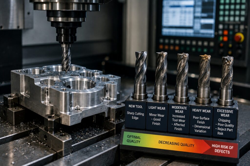
Introduction Tool wear is an unavoidable part of CNC machining. As cutting tools repeatedly remove material from a workpiece, their cutting edges gradually lose their original sharpness. If this wear is not monitored and controlled, it can affect dimensional accuracy, surface finish, tolerances, production consistency, and overall part quality . Therefore, understanding how tool wear develops and how it affects machined components is important for manufacturers producing prototypes, custom parts, low-volume batches, and production components. At Polymach365 , CNC milling, CNC turning, 3-axis, 4-axis, and 5-axis machining can support a wide range of manufacturing requirements. Proper tooling and process control are essential for producing consistent CNC machined parts. What Is Tool Wear in CNC Machining? Tool wear occurs when the cutting edge of a CNC tool gradually deteriorates during machining. Every cutting operation exposes the tool to: Friction Heat Cutting forces Material contact Vibration Repeated machining cycles Over time, these conditions can change the shape and sharpness of the cutting edge. As a result, a tool that initially produces accurate components may eventually produce different results if it is not replaced or managed appropriately. Why Does Tool Wear Matter? Tool wear directly affects the relationship between the cutting tool and workpiece. A sharp tool can remove material predictably. However, a worn tool may generate more heat, cutting forces, and friction. Consequently, excessive tool wear can contribute to: Dimensional variation Poor surface finish Burr formation Chatter Increased cutting forces Longer cycle times Reduced productivity Component rejection Therefore, monitoring tool condition is an important part of CNC quality control. Types of Tool Wear Different machining conditions can produce different forms of tool wear. 1. Flank Wear Flank wear develops along the clearance face of the cutting tool. As the flank gradually wears away, the effective cutting geometry changes. Therefore, excessive flank wear can affect dimensional accuracy and surface quality. 2. Crater Wear Crater wear develops on the rake face of the cutting tool where chips flow across the cutting edge. High temperature and continuous chip contact can contribute to crater formation. As crater wear increases, the cutting geometry can change and eventually weaken the cutting edge. 3. Chipping Chipping occurs when small pieces of the cutting edge break away. It can be associated with: Excessive cutting forces Hard materials Interrupted cuts Incorrect cutting parameters Vibration Consequently, chipping can cause sudden changes in cutting performance. 4. Thermal Wear High temperatures can accelerate tool degradation. Heat can result from: High cutting speeds Excessive friction Poor coolant application Difficult-to-machine materials Improper cutting parameters Therefore, controlling heat is important for maintaining tool performance. How Tool Wear Affects Dimensional Accuracy One of the most important effects of tool wear is dimensional variation. As the cutting edge wears, it may no longer remove material in exactly the same way as a new tool. For example, a worn tool may gradually change the size of: Holes Pockets Slots Diameters Contours Mating surfaces Therefore, components produced later in a machining run may begin to move outside their specified tolerances. This is especially important when manufacturing precision components with tight dimensional requirements. Tool Wear and Surface Finish Tool condition also has a significant effect on surface finish. A sharp cutting edge generally produces a more predictable cutting action. However, a worn tool can increase friction and vibration. As a result, the machined surface may develop: Rougher texture Visible tool marks Scratches Chatter marks Irregular surfaces Therefore, surface finish should be monitored when machining components with functional or aesthetic finishing requirements. Tool Wear and Burr Formation Burrs are unwanted raised edges that can appear after machining. A worn cutting edge may produce less efficient cutting and greater deformation near the edge of a feature. Consequently, burr formation can increase. Excessive burrs may create additional requirements for: Deburring Cleaning Finishing Inspection Therefore, maintaining suitable tool condition can help reduce unnecessary secondary operations. Tool Wear Can Increase Cutting Forces As a tool becomes worn, cutting resistance can increase. Higher cutting forces can affect both the tool and the workpiece. They may contribute to: Tool deflection Workpiece movement Vibration Chatter Dimensional variation Therefore, increasing cutting forces can be an important indication that a tool requires attention. Tool Wear and CNC Machining Cycle Time Tool wear can also affect productivity. A worn tool may require: Lower cutting speeds Additional finishing passes More frequent adjustments Extra inspection Tool replacement Consequently, excessive wear can increase the effective machining time per component. For production machining, even a small increase in cycle time can become significant when multiplied across hundreds or thousands of parts. Factors That Accelerate Tool Wear Several factors influence how quickly a CNC cutting tool wears. Cutting Speed Excessive cutting speed can increase heat generation and accelerate wear. Therefore, cutting speed should match the tool and workpiece material. Feed Rate An inappropriate feed rate can increase cutting forces or reduce cutting efficiency. Depth of Cut Heavy cuts can place greater loads on the cutting edge. Workpiece Material Harder materials can cause faster tool degradation. Materials such as hardened steel and titanium may require specialized tooling and machining parameters. Coolant Proper coolant application can help manage heat and chip evacuation. However, coolant selection and application should match the machining operation. Tool Material Carbide, coated carbide, ceramic, and other tooling materials have different performance characteristics. Therefore, tool selection should match the application. How to Detect Tool Wear Manufacturers can monitor tool conditions in several ways. Visual Inspection Inspecting the cutting edge can reveal visible wear or chipping. Dimensional Inspection Measuring machined components can reveal gradual dimensional changes. Surface Finish Inspection Changes in surface quality may indicate deteriorating tool performance. Cutting Sound Changes in machining noise can sometimes indicate vibration or tool degradation. Spindle Load Changes in machine load may indicate increased cutting resistance. Tool Monitoring Systems Modern CNC equipment can use automated monitoring technologies to detect changes in machining conditions. Therefore, combining several monitoring methods can provide better control than relying on a single indicator. How to Prevent Excessive Tool Wear Tool wear cannot be eliminated completely. However,
Why CAD Design Matters in CNC Manufacturing
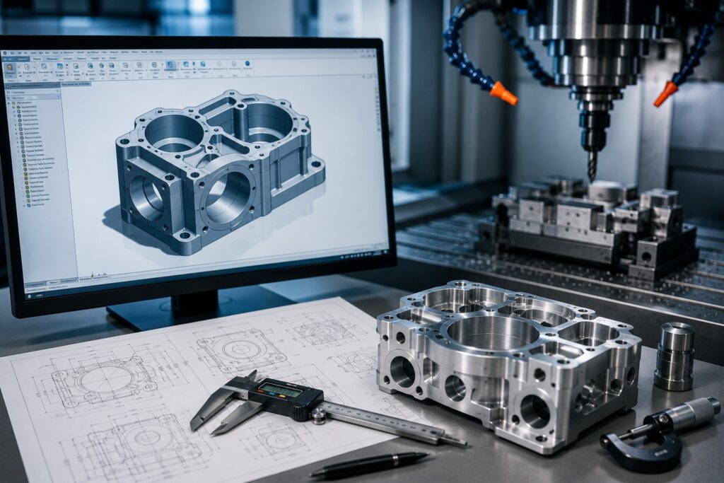
Introduction Computer-Aided Design (CAD) plays a critical role in modern CNC manufacturing. Before a CNC machine begins cutting material, manufacturers need accurate digital information that defines the part’s geometry, dimensions, tolerances, holes, features, and other manufacturing requirements . A well-prepared CAD design helps manufacturers understand exactly what needs to be produced. Furthermore, it can reduce design errors, improve machining accuracy, simplify production planning, and support better quality control. At Polymach365 , digital manufacturing connects CAD designs with CNC machining processes, including CNC milling, CNC turning, 3-axis, 4-axis, and 5-axis machining, prototype manufacturing, low-volume production, and custom machined parts. What Is CAD in CNC Manufacturing? CAD stands for Computer-Aided Design . It is used to create detailed digital models of components before they are manufactured. A CAD model can define important information such as: Part dimensions Geometry Holes and slots Curves and contours Wall thickness Internal features Mounting locations Critical surfaces Design intent Therefore, CAD provides the digital foundation for CNC manufacturing. Instead of relying only on sketches or manually interpreted drawings, manufacturers can use the digital model to prepare the machining process. How CAD Connects With CNC Machining The CNC manufacturing process typically begins with a digital design. A simplified workflow is: CAD Design → DFM Review → CAM Programming → CNC Machining → Inspection → Finished Part First, the engineer creates the component in CAD software. Next, the design can be reviewed for manufacturing ability. Then, CAM software can use the design information to create machining toolpaths. These toolpaths guide the CNC machine during cutting. As a result, accurate CAD data helps create a more reliable connection between design intent and physical production . 1. CAD Improves Machining Accuracy Accurate machining starts with accurate design information. A detailed CAD model defines the intended geometry of the component. Therefore, machinists and manufacturing engineers can work from a consistent digital reference. CAD helps to communicate: Overall dimensions Feature locations Hole positions Contours Depths Angles Critical surfaces Consequently, a properly prepared CAD model can reduce misunderstandings during manufacturing. 2. CAD Helps Identify Design Problems Early Finding a manufacturing problem after production can begin resulting in wasted material, time, and money. Therefore, reviewing the CAD model before machining is important. Manufacturers can evaluate potential issues such as: Extremely thin walls Deep cavities Difficult tool access Small internal radii Unnecessary features Complex geometries Tight tolerances As a result, engineers can make improvements before the part reaches the CNC machine. 3. CAD Supports Design for Manufactureability CAD and Design for Manufacture (DFM) work closely together. A component may function correctly in theory but still be difficult or expensive to machine. For example, a design may contain a deep narrow pocket that requires a long cutting tool. Therefore, the engineer may modify the geometry to improve tool accessibility. Similarly, unnecessarily tight tolerances can increase machining and inspection requirements. Consequently, CAD provides an excellent environment for identifying and improving these issues before production. 4. CAD Makes Complex Parts Easier to Manufacture Modern CNC machines can manufacture highly complex components. However, complex geometry requires accurate digital information. CAD models can represent: 3D contours Angled surfaces Curved profiles Deep pockets Multi-sided features Complex cavities Organic shapes Therefore, CAD is particularly important when manufacturing components that require 4-axis or 5-axis CNC machining . With an accurate model, manufacturers can develop suitable machining strategies for complex surfaces and features. 5. CAD Helps With CNC Milling CNC milling is commonly used for components containing: Pockets Slots Holes Flat surfaces Contours Mounting features Complex profiles A CAD model provides the geometry needed to create the appropriate milling toolpaths. Therefore, the quality of the CAD model can directly affect machining preparation. For example, missing or incorrect dimensions may result in additional clarification or design revisions before manufacturing can begin. 6. CAD Helps With CNC Turning CAD is equally valuable for CNC turning. Turning is commonly used to manufacture: Shafts Pins Bushings Sleeves Spacers Rollers Threaded components The CAD model can define diameters, lengths, grooves, threads, shoulders, and other rotational features. Consequently, accurate CAD information helps manufacturers prepare the turning process according to the required component geometry. 7. CAD Helps Control Tolerances Not every dimension requires the same level of precision. A CAD design can identify important dimensions and tolerances that affect component performance. Critical features may include: Bearing fits Mating surfaces Hole locations Shaft diameters Sealing surfaces Alignment features Therefore, engineers should specify tight tolerances only where they are functionally necessary. This approach can help balance performance, manufacturing ability, and cost . 8. CAD Supports Prototype Manufacturing Prototype development often involves several design changes. A typical process is: Initial CAD → Prototype → Testing → Design Changes → Revised CAD → New Prototype Therefore, CAD makes it easier to modify the design and manufacture updated versions. CNC machining can then produce functional prototypes from metals and engineering plastics. As a result, engineers can evaluate fit, assembly, dimensions, and functionality before moving into production. 9. CAD Reduces Manufacturing Errors Clear digital design information can reduce communication problems between engineers and manufacturers. A good CAD package can provide a consistent reference for: Geometry Dimensions Features Manufacturing requirements Design revisions Therefore, version control is also important. Manufacturers should work from the approved and current CAD version to avoid producing outdated designs. 10. CAD Supports Faster Production Planning Manufacturers need to understand the component before deciding how to machine it. The CAD model helps them evaluate: Machine requirements Tool accessibility Workholding Number of setups Machining orientation Cutting strategy Material removal Consequently, a well-prepared CAD model can simplify production planning. This is particularly valuable for custom parts and complex CNC components. CAD File Formats for CNC Machining Different manufacturing platforms and CNC workflows may support different CAD formats. Common formats include: STEP STP IGES IGS STL SLDPRT Among these, STEP files are widely used for exchanging 3D CAD data between different software systems. However, the preferred format depends on the manufacturing workflow and required information. Therefore, it is important to provide the correct file format when requesting a
CNC Machining for Small Businesses A Practical Manufacturing Guide
Introduction CNC machining gives small businesses access to accurate, repeatable manufacturing without requiring large production volumes. From custom components and prototypes to replacement parts and small-batch production , CNC machining can help businesses turn digital designs into functional physical parts. For a small business, however, choosing the right machining process, material, quantity, tolerances, and supplier is important for controlling costs and avoiding unnecessary production delays. This guide explains how CNC machining works for small businesses, when it makes sense, what factors affect cost, and how to prepare a project for successful manufacturing. What is CNC Machining? CNC machining is a computer-controlled manufacturing process that removes material from a solid workpiece to create a finished component. A CNC machine follows programmed instructions generated from a digital CAD design. Depending on the machine and part geometry, operations such as milling, turning, drilling, boring, threading, and contouring can be performed. Common CNC machining processes include: CNC milling CNC turning CNC lathe machining 3-axis machining 4-axis machining 5-axis machining This flexibility makes CNC machining suitable for businesses manufacturing everything from simple brackets to complex mechanical components. Why Is CNC Machining Useful for Small Businesses? Large manufacturers often have dedicated production lines and high-volume orders. Small businesses may have very different requirements. They may need: A few prototype parts Small production batches Custom machine components Replacement parts Engineering samples Specialized fixtures Custom tooling CNC machining can accommodate these requirements without requiring permanent tooling dedicated to a single plastic part design. As a result, small businesses can use CNC machining to manufacture parts according to their current production needs. CNC Machining for Prototypes Product development is one of the most useful applications of CNC machining for small businesses. Instead of moving directly from CAD design to large-scale production, a business can manufacture a prototype first. A typical workflow is: CAD Design → CNC Prototype → Testing → Design Changes → Final Design → Production A machined prototype can help evaluate: Physical dimensions Assembly Fit Function Strength Usability Design problems Therefore, CNC machining can help small businesses validate products before shipping to larger quantities. CNC Machining for Small-Batch Production Not every business needs thousands of parts. Small-batch CNC machining can be useful for: New products Specialized equipment Industrial components Custom products Pilot production Replacement parts Limited-market products For businesses with unpredictable demand, producing smaller quantities can also reduce the risk of holding excessive inventory. CNC Milling or CNC Turning: Which Does Your Business Need? The right CNC process depends largely on the geometry of the component. CNC Milling CNC milling is generally suitable for components containing: Pockets Slots Flat surfaces Holes Complex contours Multi-sided features Typical examples include brackets, housings, mounting plates, fixtures, and custom machine components. CNC Turning CNC turning is generally suitable for rotational components such as: Shafts Pins Bushings Spacers Sleeves Rollers Cylindrical components If your part combines cylindrical and non-cylindrical features, it may require both turning and milling operations. Choosing the Right Material Material selection is another important consideration for small businesses. Common CNC machining materials include: Aluminum Stainless steel Carbon steel Brass Copper Titanium ABS Nylon Delrin Polycarbonate PEEK Aluminum A popular option for lightweight components and prototypes because of its useful strength-to-weight ratio and machinability. Stainless Steel Suitable for applications requiring strength and corrosion resistance. Brass Often used for fittings, bushings, connectors, and other components where machinability is important. Engineering Plastics Materials such as Nylon, Delrin, and PEEK can be useful when a component requires lower weight, electrical insulation, chemical resistance, or other specific properties. The best material depends on the part’s operating environment, strength requirements, temperature exposure, and intended application. What Affects CNC Machining Cost for Small Businesses? CNC machining costs vary from project to project. Several factors can influence the final price. Material The cost and machinability of the selected material affect the overall manufacturing cost. Part Complexity A simple component may require only a few machining operations, while a complex component can require multiple tools and setups. Machining Time Longer cutting times generally increase production costs. Number of Setups Components requiring multiple orientations may require additional setup work. Tolerances Very tight tolerances can require additional process control and inspection. Surface Finish Additional finishing requirements can increase production time and cost. Quantity The number of parts can significantly affect the economics of the project. Therefore, small businesses should consider the complete manufacturing requirement rather than focusing only on the initial machining price. How Small Businesses Can Reduce CNC Machining Costs Avoid Unnecessary Tight Tolerances Only specify tight tolerances where they are necessary for the function or assembly of the component. Simplify the Design Removing unnecessary features can reduce machining operations. Choose Practical Materials A readily machinable material may reduce manufacturing time compared with a more difficult material when both meet the application’s requirements. Reduce Setups Designing parts with machining accessibility in mind can help reduce the number of setups. Order the Appropriate Quantity Ordering too few parts can increase the per-part cost because setup costs are distributed across fewer components. Use DFM Principles Design for Manufacturing, or DFM, helps engineers create parts that are easier and more economical to manufacture. As a result, a manufacturing-friendly design can often provide better cost control. Why CAD Files Matter A clear CAD file gives the manufacturer the information needed to understand the component geometry. Common file formats may include: STEP STP IGES IGS STL DXF For CNC machining, 3D solid models such as STEP files are often useful for understanding complex component geometry. A technical drawing can also communicate important requirements such as: Critical dimensions Tolerances Threads Surface finish Material Special notes Therefore, providing complete design information can make quoting and manufacturing more simple. What Should a Small Business Provide When Requesting a CNC Quote? To receive a useful manufacturing quotation, provide as much relevant information as possible. 1. CAD File Provide the latest approved design. 2. Material Specify the required material and grade where applicable. 3. Quantity State how many components you need. 4. Tolerances Identify critical tolerances rather than
How DFM Improves CNC Machined Part Quality and Reduces Production Costs
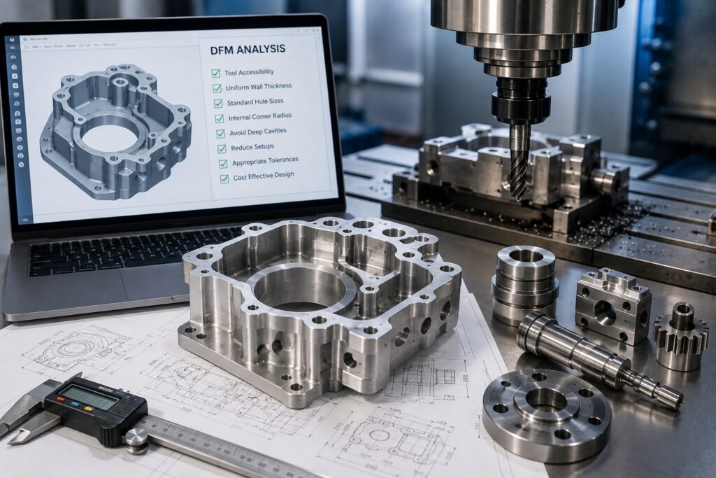
Introduction Design for Manufacturability (DFM) is an important part of CNC machining because the way a component is designed directly affects how easily, accurately, and efficiently it can be manufactured. Part may look perfect in CAD software, but that doesn’t always mean it is practical to machine. Difficult-to-access features, unnecessarily tight tolerances, deep cavities, thin walls, and complicated setups can increase machining time and production costs. Therefore, applying DFM principles before manufacturing begins can help engineers create parts that are easier to machine, more consistent, and more cost-effective . At Polymach365 , we support CNC milling, CNC turning, 3-axis, 4-axis, and 5-axis machining, prototype manufacturing, low-volume production, custom CNC machining, and precision machined components. A DFM-focused approach can help connect your design requirements with a practical manufacturing process. What Is Design for Manufacture? Design for Manufacture means designing a component with the manufacturing process in mind. For CNC machining, DFM considers factors such as: Part geometry Material selection Tolerances Wall thickness Internal corners Hole sizes Tool accessibility Machining orientation Number of setups Surface finish Production quantity Instead of designing a component first and worrying about manufacturing later, DFM encourages engineers to consider manufacturing ability from the beginning. As a result, potential manufacturing problems can be identified before production starts. Why Is DFM Important for CNC Machining? CNC machines can manufacture highly complex components. However, complexity often comes with additional manufacturing requirements. For example, a deep and narrow cavity may require a long cutting tool. However, long tools can be more susceptible to vibration and deflection. Similarly, extremely tight tolerances may require additional finishing operations and inspection. Therefore, a DFM review can identify these challenges early and help engineers make practical design decisions. 1.DFM Improves CNC Machined Part Quality One of the biggest benefits of DFM is improved manufacturing consistency. A manufacturing design allows cutting tools to reach the required features more effectively. It can also reduce unnecessary setups and minimize difficult machining operations. Consequently, manufacturers can achieve more predictable results. DFM can help improve: Dimensional accuracy Repeatability Surface finish Feature consistency Assembly fit Overall part quality Therefore, DFM is not only about reducing cost. It also contributes directly to the quality of the finished component. 2. DFM Reduces Unnecessary Tight Tolerances Tolerances define how much a dimension can vary from its nominal value. While tight tolerances are essential for certain functional features, applying them to every dimension can make a component unnecessarily expensive to manufacture. Tighter tolerances may require: Additional machining operations More precise tooling Additional inspection Longer cycle times Specialized processes Therefore, engineers should identify which dimensions are genuinely critical. Better Approach Instead of specifying extremely tight tolerances throughout the entire component, use tighter tolerances only where they affect: Mating components Bearing fits Sealing surfaces Critical alignment Functional movement As a result, the part can maintain its required performance without unnecessary manufacturing complexity. 3. DFM Simplifies Part Geometry Complex geometry can increase machining time and programming requirements. Some complex features may also require specialized tooling or multi-axis machining. Therefore, simplifying the geometry where possible can improve manufacturing ability. For example, unnecessary pockets, grooves, or decorative features may increase machining time without providing a functional benefit. A DFM review asks an important question: Does every feature serve a purpose? If the answer is no, removing that feature may reduce both machining time and cost. 4. DFM Improves Tool Accessibility Cutting tools need sufficient access to the features they are machining. Deep cavities, narrow slots, and obstructed surfaces can make tool access difficult. Therefore, designers should consider tool accessibility while developing the CAD model. Poor tool access can result in: Longer machining times Specialized tooling Additional setups Tool deflection Reduced surface quality As a result, designing features with practical tool access can make CNC machining more efficient. 5. DFM Helps Control Internal Corner Radii CNC milling tools are generally round. Therefore, creating perfectly sharp internal corners is difficult with conventional milling. Instead, internal corners normally require a radius. Why Does This Matter? If a design includes a very small internal corner radius, the manufacturer may need a smaller cutting tool. However, smaller tools can require slower cutting conditions and may increase machining time. Therefore, using the largest practical internal radius can often improve machining efficiency. 6. DFM Reduces the Number of CNC Setups Every additional setup can add time and increase positioning requirements. A component that requires machining from several directions may need multiple repositioning operations. Therefore, designers should consider whether the part can be manufactured with fewer setups. Multi-axis machining can sometimes provide better access to multiple surfaces. However, not every component needs 5-axis machining. Consequently, the goal should be to choose a design and machining strategy that provides the required features with an efficient number of setups. 7. DFM Helps Prevent Thin-Wall Problems Thin walls can be difficult to machine because cutting forces may cause vibration or deformation. Therefore, unnecessarily thin sections should be avoided when the application allows. A stronger and more stable design can help improve: Machining stability Dimensional consistency Surface finish Part rigidity However, the appropriate wall thickness depends on the material, geometry, part size, and machining strategy. Therefore, wall thickness should be evaluated together with the complete component design. 8. DFM Reduces Machining Time Machining time is an important factor in CNC production costs. Several design decisions can increase machining time, including: Excessive material removal Deep pockets Very small features Complex toolpaths Tight tolerances Multiple setups Therefore, simplifying the design can reduce unnecessary machining operations. For example, reducing a deep pocket or eliminating a non-functional feature may significantly simplify the machining process. As a result, DFM can help shorten cycle times and improve production efficiency. 9. DFM Helps Reduce Tool Wear Tool wear can affect both quality and production costs. Difficult-to-machine designs may require aggressive toolpaths, long cutting tools, or small-diameter tools. These conditions can increase tool wear. Therefore, designing parts with practical feature sizes and accessible geometry can help manufacturers use tooling more efficiently. This can contribute to: Longer tool life More consistent
CNC Machining for Small Businesses A Practical Manufacturing Guide
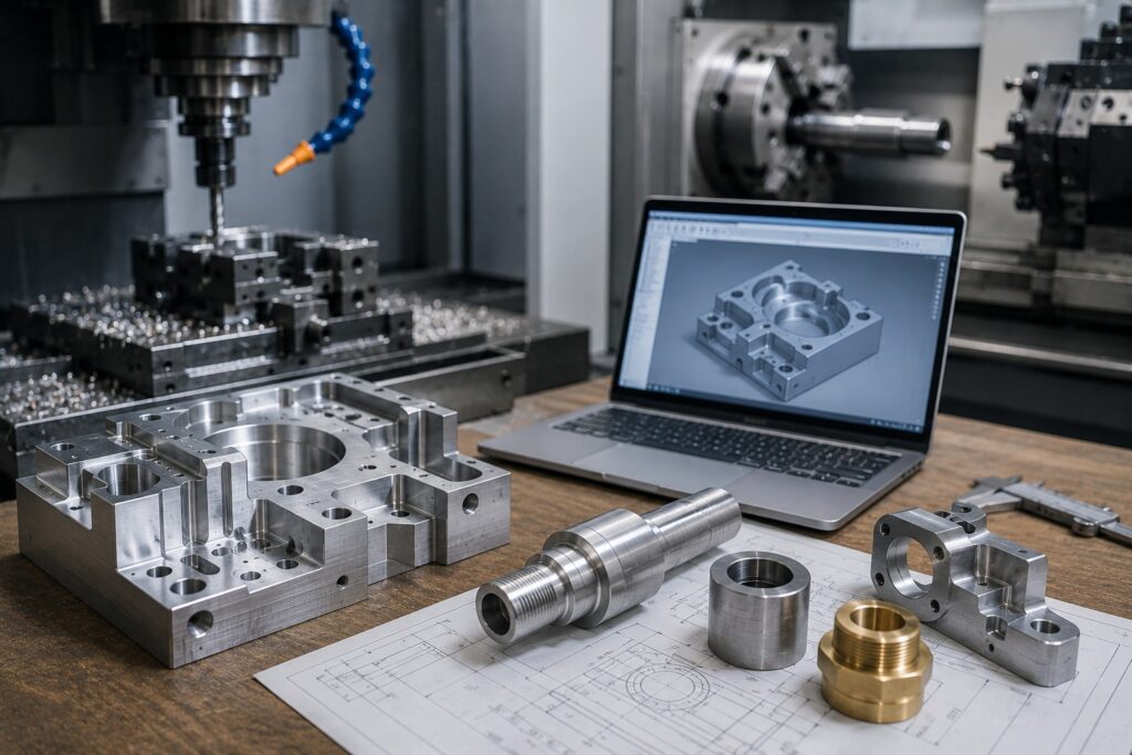
Introduction CNC machining gives small businesses access to accurate, repeatable manufacturing without requiring large production volumes. From custom components and prototypes to replacement parts and small-batch production , CNC machining can help businesses turn digital designs into functional physical parts. For a small business, however, choosing the right machining process, material, quantity, tolerances, and supplier is important for controlling costs and avoiding unnecessary production delays. This guide explains how CNC machining works for small businesses, when it makes sense, what factors affect cost, and how to prepare a project for successful manufacturing. What is CNC Machining? CNC machining is a computer-controlled manufacturing process that removes material from a solid workpiece to create a finished component. A CNC machine follows programmed instructions generated from a digital CAD design. Depending on the machine and part geometry, operations such as milling, turning, drilling, boring, threading, and contouring can be performed. Common CNC machining processes include: CNC milling CNC turning CNC lathe machining 3-axis machining 4-axis machining 5-axis machining This flexibility makes CNC machining suitable for businesses manufacturing everything from simple brackets to complex mechanical components. Why Is CNC Machining Useful for Small Businesses? Large manufacturers often have dedicated production lines and high-volume orders. Small businesses may have very different requirements. They may need: A few prototype parts Small production batches Custom machine components Replacement parts Engineering samples Specialized fixtures Custom tooling CNC machining can accommodate these requirements without requiring permanent tooling dedicated to a single plastic part design. As a result, small businesses can use CNC machining to manufacture parts according to their current production needs. CNC Machining for Prototypes Product development is one of the most useful applications of CNC machining for small businesses. Instead of moving directly from CAD design to large-scale production, a business can manufacture a prototype first. A typical workflow is: CAD Design → CNC Prototype → Testing → Design Changes → Final Design → Production A machined prototype can help evaluate: Physical dimensions Assembly Fit Function Strength Usability Design problems Therefore, CNC machining can help small businesses validate products before shipping to larger quantities. CNC Machining for Small-Batch Production Not every business needs thousands of parts. Small-batch CNC machining can be useful for: New products Specialized equipment Industrial components Custom products Pilot production Replacement parts Limited-market products For businesses with unpredictable demand, producing smaller quantities can also reduce the risk of holding excessive inventory. CNC Milling or CNC Turning: Which Does Your Business Need? The right CNC process depends largely on the geometry of the component. CNC Milling CNC milling is generally suitable for components containing: Pockets Slots Flat surfaces Holes Complex contours Multi-sided features Typical examples include brackets, housings, mounting plates, fixtures, and custom machine components. CNC Turning CNC turning is generally suitable for rotational components such as: Shafts Pins Bushings Spacers Sleeves Rollers Cylindrical components If your part combines cylindrical and non-cylindrical features, it may require both turning and milling operations. Choosing the Right Material Material selection is another important consideration for small businesses. Common CNC machining materials include: Aluminum Stainless steel Carbon steel Brass Copper Titanium ABS Nylon Delrin Polycarbonate PEEK Aluminum A popular option for lightweight components and prototypes because of its useful strength-to-weight ratio and machinability. Stainless Steel Suitable for applications requiring strength and corrosion resistance. Brass Often used for fittings, bushings, connectors, and other components where machinability is important. Engineering Plastics Materials such as Nylon, Delrin, and PEEK can be useful when a component requires lower weight, electrical insulation, chemical resistance, or other specific properties. The best material depends on the part’s operating environment, strength requirements, temperature exposure, and intended application. What Affects CNC Machining Cost for Small Businesses? CNC machining costs vary from project to project. Several factors can influence the final price. Material The cost and machinability of the selected material affect the overall manufacturing cost. Part Complexity A simple component may require only a few machining operations, while a complex component can require multiple tools and setups. Machining Time Longer cutting times generally increase production costs. Number of Setups Components requiring multiple orientations may require additional setup work. Tolerances Very tight tolerances can require additional process control and inspection. Surface Finish Additional finishing requirements can increase production time and cost. Quantity The number of parts can significantly affect the economics of the project. Therefore, small businesses should consider the complete manufacturing requirement rather than focusing only on the initial machining price. How Small Businesses Can Reduce CNC Machining Costs Avoid Unnecessary Tight Tolerances Only specify tight tolerances where they are necessary for the function or assembly of the component. Simplify the Design Removing unnecessary features can reduce machining operations. Choose Practical Materials A readily machinable material may reduce manufacturing time compared with a more difficult material when both meet the application’s requirements. Reduce Setups Designing parts with machining accessibility in mind can help reduce the number of setups. Order the Appropriate Quantity Ordering too few parts can increase the per-part cost because setup costs are distributed across fewer components. Use DFM Principles Design for Manufacturing, or DFM, helps engineers create parts that are easier and more economical to manufacture. As a result, a manufacturing-friendly design can often provide better cost control. Why CAD Files Matter A clear CAD file gives the manufacturer the information needed to understand the component geometry. Common file formats may include: STEP STP IGES IGS STL DXF For CNC machining, 3D solid models such as STEP files are often useful for understanding complex component geometry. A technical drawing can also communicate important requirements such as: Critical dimensions Tolerances Threads Surface finish Material Special notes Therefore, providing complete design information can make quoting and manufacturing more simple. What Should a Small Business Provide When Requesting a CNC Quote? To receive a useful manufacturing quotation, provide as much relevant information as possible. 1. CAD File Provide the latest approved design. 2. Material Specify the required material and grade where applicable. 3. Quantity State how many components you need. 4. Tolerances Identify critical tolerances rather than
Prototype Machining vs Production Machining: Understanding the Difference
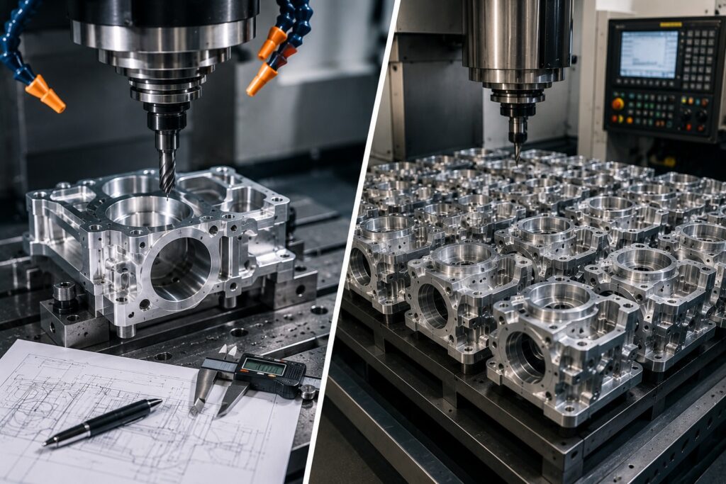
Choosing the Right CNC Machining Approach for Your Project Product development often involves several manufacturing stages. A component may begin as a single prototype and later move into small-batch or larger-scale production. Therefore, understanding the difference between prototype machining and production machining can help manufacturers choose the right process, control costs, and plan their projects more effectively. Both approaches use CNC machining technology, but their goals are different. Prototype machining focuses primarily on design validation, testing, and development , while production machining focuses on repeatability, efficiency, consistency, and manufacturing larger quantities . At Polymach365 , we provide CNC milling, CNC turning, 3-axis, 4-axis, and 5-axis machining, prototype manufacturing, low-volume production, custom CNC machining, and precision machined components. What is Prototype Machining? Prototype machining is the process of manufacturing a physical component based on a CAD model or engineering drawing for testing and product development. Instead of immediately producing a large quantity, manufacturers create one or a small number of parts to evaluate the design. Prototype machining can help engineers test: Part dimensions Fit and assembly Function Strength Clearances Material selection Surface finish Design performance Therefore, prototype machining provides an important step between digital design and final production. What Is Production Machining? Production machining focuses on manufacturing components repeatedly according to established specifications. Once a design has been tested and approved, the manufacturing process can be optimized for producing the required quantity. Production machining typically emphasizes: Repeatability Dimensional consistency Production efficiency Tool life Process control Quality inspection Cost management As a result, production machining is better suited to projects where the same component must be manufactured consistently over multiple production runs. Prototype Machining vs Production Machining Although both processes use CNC equipment, their priorities can differ considerably. Feature Prototype Machining Production Machining Main Purpose Design validation Repeatable manufacturing Typical Quantity One or a few parts Larger quantities Design Changes Frequent Usually controlled Priority Flexibility Efficiency Tooling Often flexible Optimized for production Process Development-focused Standardized Cost Focus Development cost Cost per part Inspection Design validation Consistent quality control Lead Time Often prioritized Planned production schedule Therefore, choosing between prototype and production machining depends largely on the development stage and required quantity. 1. Different Manufacturing Goals The biggest difference is the purpose of manufacturing. Prototype Machining The objective is to answer questions such as: Does the design work? Does the component fit correctly? Does the material perform as expected? Are any design changes required? Production Machining The objective changes to: Can we manufacture this component consistently? Can we maintain the required tolerances? Can we produce the required quantity efficiently? Therefore, prototype machining is primarily development-focused, while production machining is manufacturing-focused. 2. Production Quantity Quantity is another important difference. Prototype machining may involve: Part 1 2 parts 5 parts Small prototype batches Production machining can involve significantly larger quantities depending on the project. However, CNC machining is also suitable for low-volume production , where manufacturers need more parts than a prototype but do not require mass production. Therefore, there is not always a sharp boundary between prototype and production machining. 3. Design Changes Prototype projects often involve design revisions. After testing the first prototype, engineers may modify: Dimensions Hole locations Wall thickness Mounting features Geometry Material Surface finish The next prototype can then be manufactured using the updated CAD model. In production machining, however, the design is generally more established. Therefore, uncontrolled design changes during production can create additional costs and process complications. 4. Tooling Strategy Manufacturers may use standard tooling and workholding methods that allow the component to be produced quickly. Production machining, on the other hand, may justify optimized: Cutting tools Toolpaths Fixtures Workholding Tool-change strategies As a result, production machining can achieve greater efficiency when manufacturing repeated quantities. 5. Cost Considerations Prototype machining and production machining have different cost structures. A prototype may have a higher per-part cost because setup and programming costs are distributed across only a few components. Production machining can reduce the average cost per component as the quantity increases. However, higher production volumes may require additional process optimization. Therefore, the cheapest option is not always determined by the machining price alone. You should also consider development costs, tooling, setup, inspection, finishing, and production quantity. 6. Lead Time Prototype projects often prioritize fast development. Engineers may need a physical part quickly so they can test and modify the design. Production machining usually follows a planned manufacturing schedule. The process may include: Production Planning → Material Preparation → CNC Machining → Inspection → Finishing → Delivery Therefore, lead time depends on the part’s complexity, material, quantity, tolerances, finishing requirements, and manufacturing process. CNC Machining for Prototype Development CNC machining is particularly useful for functional prototypes because it can produce parts directly from digital designs. A typical workflow is: CAD Design → DFM Review → Prototype Machining → Testing → Design Review This process allows engineers to evaluate a real component rather than relying entirely on digital simulations. Furthermore, CNC prototypes can often be manufactured from production-grade materials. As a result, engineers can obtain a more realistic understanding of how the final component may perform. CNC Machining for Production Manufacturing Once the design has been validated, production machining can begin. A production workflow may include: Approved CAD → Process Planning → CAM Programming → CNC Machining → Inspection → Finishing → Production Delivery At this stage, manufacturers can optimize the process for consistency and efficiency. Important considerations include: Tool life Cycle time Workholding Material handling Inspection Repeatability Production scheduling Consequently, production machining focuses on making the established process reliable over repeated manufacturing cycles. Low-Volume Production: The Middle Ground Some projects fail between prototyping and mass production. For example, a manufacturer may need 20, 50, or 100 components for a specialized application. In these situations, low-volume CNC machining can provide a practical solution. It can support: Small production batches Pilot production Product validation Specialized equipment Replacement parts Engineering changes Therefore, manufacturers do not always need to move directly from one prototype to high-volume production. Prototype Machining for Product Development Prototype
What Is CNC Milling? A Complete Guide for Manufacturers
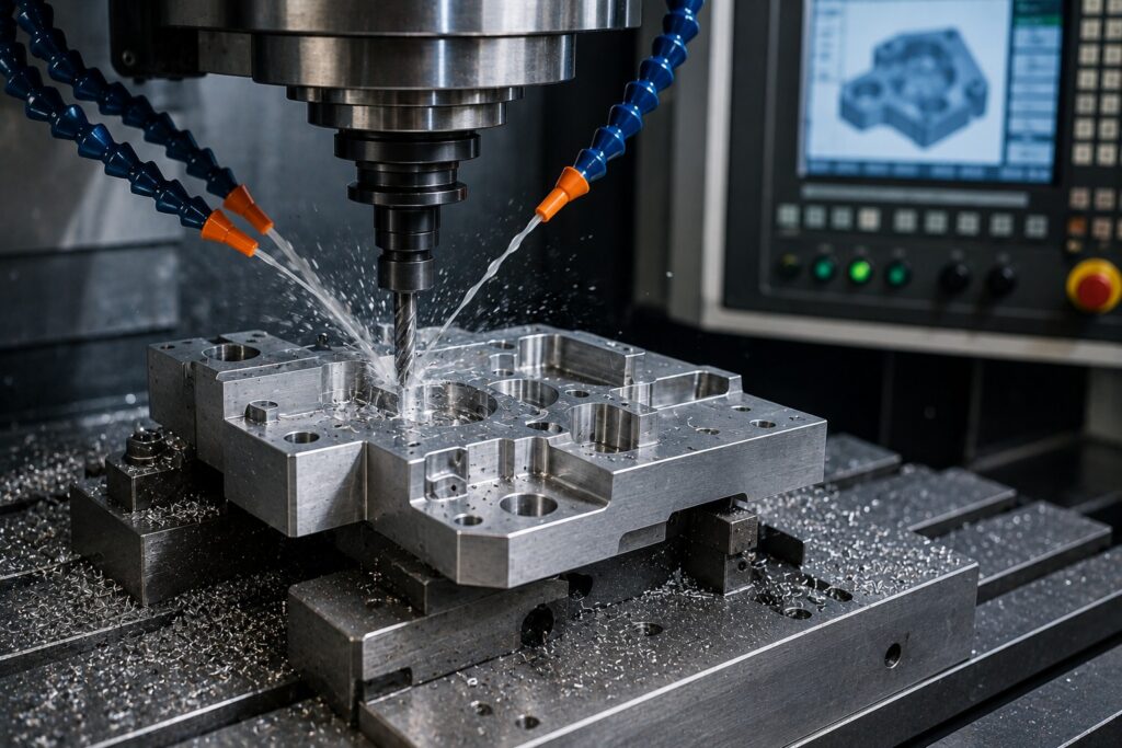
Introduction CNC milling is one of the most widely used manufacturing processes for producing custom metal parts, plastic components, prototypes, tooling, and precision machine components. It uses computer-controlled cutting tools to remove material from a workpiece and create a finished component based on a digital CAD design. Unlike manual machining, CNC milling provides automated and repeatable tool movement. Therefore, manufacturers can produce complex geometries, accurate holes, pockets, slots, contours, and other features with consistent results. For manufacturers, engineers, and product developers, understanding how CNC milling works, which machines are available, what materials can be machined, and when to use CNC milling can help make better manufacturing decisions. At Polymach365, CNC manufacturing solutions support custom components, prototypes, low-volume production, and production requirements using modern CNC machining processes. What Is CNC Milling? CNC milling is a subtractive manufacturing process that uses computer-controlled cutting tools to remove material from a solid workpiece. The term CNC means Computer Numerical Control. A CNC milling machine follows programmed instructions to control the movement of the cutting tool and, depending on the machine configuration, the workpiece. The process can create a wide range of features, including: Holes Slots Pockets Threads Contours Flat surfaces Angled surfaces Complex 3D profiles Therefore, CNC milling is suitable for both relatively simple components and highly complex parts. How Does CNC Milling Work? The CNC milling process starts with a digital design and ends with an inspected machined component. A typical workflow is: CAD Design → DFM Review → CAM Programming → Material Preparation → CNC Milling → Inspection → Finishing → Finished Part 1. Create the CAD Model The engineer creates a 2D drawing or 3D CAD model of the required component. The design defines the part’s geometry, dimensions, holes, pockets, contours, and other features. 2. Review the Design Before machining, the design can be reviewed for manufacturability. This step helps identify issues such as: Difficult tool access Extremely thin walls Deep pockets Small internal radii Unnecessary tight tolerances As a result, manufacturers can address potential production problems before machining begins. 3. Prepare the CAM Program CAM software converts the CAD geometry into machining toolpaths. The program determines how the cutting tool should move, including: Tool selection Cutting paths Cutting depth Feed rate Spindle speed Machining sequence 4. Set Up the CNC Machine The workpiece is secured using suitable workholding. The cutting tools are installed, and the machine is prepared according to the programmed operation. 5. Machine the Component The CNC machine follows the programmed toolpaths to remove material. Depending on the design, several tools may be used to perform roughing, drilling, contouring, pocketing, and finishing operations. 6. Inspect the Finished Part After machining, the component can be inspected to verify dimensions and other project requirements. Therefore, inspection helps confirm that the finished part matches the approved design. What Can a CNC Milling Machine Produce? CNC milling can produce many different component geometries. Common examples include: Mechanical Components Brackets Mounting plates Housings Frames Fixtures Spacers Precision Components Machine components Custom tooling Functional prototypes Assembly components Precision inserts Complex Components Mold components Complex housings Multi-sided parts Components with angled surfaces 3D contoured parts Therefore, CNC milling can support a wide range of manufacturing applications. Types of CNC Milling Machines Different CNC milling configurations are available depending on the component requirements. 3-Axis CNC Milling A 3-axis machine typically moves the cutting tool along three primary axes. It is suitable for many standard components containing: Pockets Holes Slots Flat surfaces Basic contours Therefore, 3-axis milling is a practical option for many general-purpose CNC components. 4-Axis CNC Milling A 4-axis machine adds rotational movement to the standard linear axes. This can allow manufacturers to access additional surfaces without completely repositioning the component. As a result, 4-axis machining can be useful for parts requiring features around multiple sides. 5-Axis CNC Milling 5-axis CNC machining provides additional movement and tool orientation capabilities. It is particularly useful for complex components containing: Angled surfaces Deep cavities Complex contours Multi-sided features Difficult-to-access geometries Therefore, 5-axis milling can reduce the need for multiple setups in suitable applications. CNC Milling vs CNC Turning CNC milling and CNC turning are both subtractive manufacturing processes, but they work differently. CNC milling generally uses rotating cutting tools to remove material from a workpiece. CNC turning rotates the workpiece while a cutting tool removes material. Therefore: Milling is often suitable for prismatic and complex multi-feature parts. Turning is generally suited to cylindrical and rotational components. Some components may require both processes. For example, a part could be turned to create its primary cylindrical geometry and then milled to add slots, holes, or flat surfaces. Materials Used for CNC Milling CNC milling can be used with a broad range of materials. Aluminum Aluminum is widely used because it combines: Low weight Good machinability Useful strength Corrosion resistance It is commonly used for prototypes, housings, brackets, machine components, and other custom parts. Stainless Steel Stainless steel is often selected when strength and corrosion resistance are important. It can be used for industrial components, mechanical parts, and equipment applications. Carbon Steel Carbon steel can provide strength and durability for various mechanical components. Brass Brass offers good machinability and is frequently used for fittings, bushings, connectors, and other components. Copper Copper is useful where electrical or thermal conductivity is important. Titanium Titanium provides high strength relative to its weight and can be useful for demanding applications. However, it generally requires more careful machining conditions. Engineering Plastics CNC milling can also machine materials such as: ABS Nylon Delrin Polycarbonate PEEK PTFE Therefore, material selection should depend on the component’s performance requirements as well as machining considerations. What Are the Advantages of CNC Milling? High Repeatability Once the machining process has been programmed correctly, CNC equipment can repeat the same operations consistently. Therefore, CNC milling is suitable for producing multiple components with consistent geometry. Complex Geometries Modern CNC milling machines can produce intricate shapes that may be difficult to manufacture using conventional machining methods. Design Flexibility Because CNC machining works from digital
How to Choose the Right CNC Machining Process for Your Part
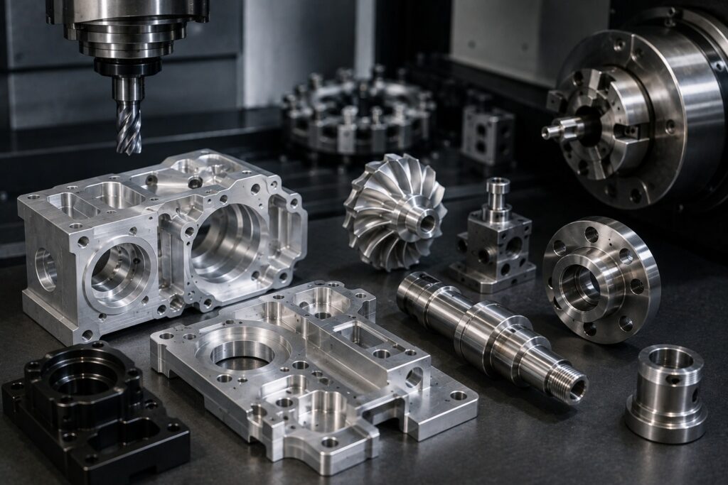
How to Choose the Right CNC Machining Process for Your Part Choosing the right CNC machining process is essential for achieving the required accuracy, surface finish, production speed, and cost . Different parts require different machining methods, and selecting the wrong process can increase manufacturing time, tooling requirements, and overall production costs. Whether you are developing a prototype, manufacturing a custom component, or producing a larger batch, understanding the differences between CNC milling, CNC turning, and multi-axis machining can help you make a better manufacturing decision. At Polymach365 , we provide CNC milling, CNC turning, 3-axis, 4-axis, and 5-axis machining, prototype manufacturing, low-volume production, custom CNC machining, and precision machined components. What Is a CNC Machining Process? CNC machining uses computer-controlled equipment to remove material from a workpiece according to a digital design. The machining process can include operations such as: Milling Turning drilling Boring Threading Tapping Reaming Contouring Pocketing Therefore, the best machining process depends on the shape, material, dimensions, tolerances, quantity, and application of your part. What Factors Should You Consider? Before choosing a CNC machining process, evaluate several important factors. 1. Part Geometry The shape of your component is one of the most important considerations. A flat component with pockets and holes may be suitable for CNC milling, while a cylindrical shaft may be better suited to CNC turning. Complex parts with features on several sides may require multi-axis machining. Therefore, always begin by analyzing the geometry of the part. 2. Material Selection The material can also influence the machining process. Common CNC materials include: Aluminum Stainless steel Carbon steel Tool steel Brass Copper Titanium ABS Nylon Delrin Polycarbonate PEEK Different materials have different levels of hardness, machinability, heat generation, and tool wear. For example, aluminum is generally easy to machine, while titanium may require more controlled cutting conditions. Consequently, the selected machining process and tooling should match the material. 3. Required Tolerances Your required tolerances can influence the machining strategy. Some components only require standard dimensional accuracy, while others contain critical features that need tighter tolerances. Important features may include: Precision holes Shaft diameters Mating surfaces Mounting locations Sealing surfaces Bearing fits Therefore, identify critical tolerances before selecting the machining process. 4. Part Size The physical size of the component can determine which CNC machine is appropriate. Large components may require machines with larger work envelopes, while small precision components may benefit from specialized equipment. Therefore, provide the part dimensions when requesting a machining quote so the manufacturer can determine suitable equipment. CNC Milling: When Should You Choose It? CNC milling is one of the most versatile machining processes. During milling, rotating cutting tools remove material from a stationary workpiece. CNC milling is particularly suitable for components containing: Pockets Slots Holes Flat surfaces Contours Mounting features Complex profiles Typical CNC Milling Applications Braces Housings Mounting plates Fixtures Machine components Mold components Custom tooling Therefore, milling is often the preferred option for prismatic and complex non-cylindrical components. CNC Turning: When Should You Choose It? CNC turning is designed primarily for rotational components. During turning, the workpiece rotates while a cutting tool removes material. It is suitable for: Shafts Pins Bushings Sleeves Spacers Rollers Couplings Threaded components Therefore, if your component is primarily cylindrical or rotational, CNC turning may be more efficient than milling. 3-Axis CNC Machining 3-axis machining moves the cutting tool along three primary axes. It is suitable for many conventional components with accessible surfaces. Typical applications include: Plates Braces Simple housings Fixtures Mounting components The main advantage is that 3-axis machining can provide an efficient solution for many simple geometries. Therefore, you should not automatically choose a more advanced machining process when a 3-axis solution can meet the requirements. 4-Axis CNC Machining 4-axis machining introduces an additional rotational movement. This can provide better access to multiple surfaces without manually repositioning the workpiece as often. It can be useful for components requiring: Multiple-sided machining Radial features Angled holes Complex positioning Consequently, 4-axis machining can provide a useful middle ground between conventional 3-axis machining and more advanced 5-axis processes. 5-Axis CNC Machining 5-axis machining provides additional movement between the cutting tool and workpiece. It is particularly useful for complex components containing: Angled surfaces Complex contours Deep cavities Multi-sided features Difficult-to-access areas Organic geometries One major advantage is the potential to reduce the number of setups required. Therefore, 5-axis machining can improve access to complex features while helping maintain positional relationships between surfaces. However, 5-axis machining is not automatically the best option for every part. If a simpler process can produce the component efficiently, it may provide better overall value. How to Choose Between Milling and Turning A simple way to determine the appropriate process is to consider the dominant geometry. Part Characteristic Suitable Process Cylindrical component CNC Turning Shafts and pins CNC Turning Flat plates CNC Milling Pockets and slots CNC Milling Complex 3D surfaces CNC Milling / 5-Axis Multi-sided geometry 4-Axis / 5-Axis Radial features CNC Turning / 4-Axis Complex angled features 5-Axis CNC Machining Therefore, the geometry should be the starting point when selecting a machining process. Consider the Number of Setups Every time a workpiece is repositioned, additional setup time may be required. Multiple setups can also introduce positioning variation. Therefore, reducing unnecessary setups can improve: Production efficiency Repeatability Machining time Overall cost For suitable complex components, multi-axis machining can reduce the number of repositioning operations. Consider Production Quantity Production volume also affects process selection. Prototypes For prototypes, flexibility is often more important than maximizing production speed. CNC machining can produce functional prototypes directly from CAD models. Low-Volume Production For small batches, CNC machining can provide flexibility without requiring dedicated high-volume tooling. Larger Production Runs For larger quantities, manufacturers may optimize: Toolpaths Workholding Cutting parameters Tool life Inspection procedures Therefore, the same component may use different manufacturing strategies depending on production volume. Consider Surface Finish Requirements Surface finish can influence tooling and machining strategy. A component may require: Standard machined finish Smoother machined finish Polishing Brushing Anodizing Plating Powder coating Therefore, communicate the
CNC Machining for Aerospace Components: Key Considerations
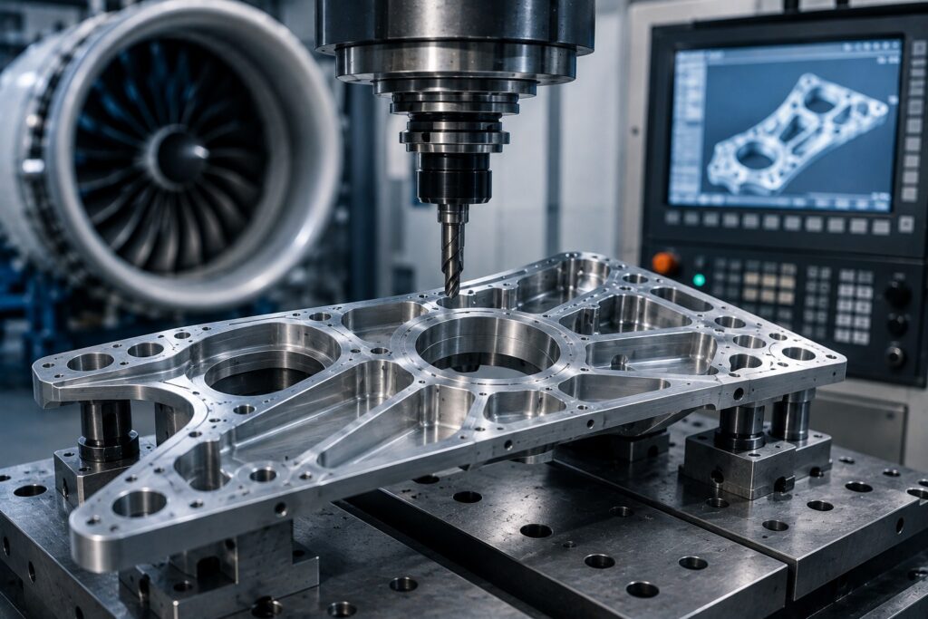
Precision Manufacturing for Aerospace Parts The aerospace industry demands components that meet strict requirements for dimensional accuracy, material performance, repeatability, surface quality, and manufacturing consistency . Even a small variation in a critical component can affect assembly, performance, or reliability. CNC machining provides the flexibility required to manufacture many aerospace components from metals and engineering materials. With advanced CNC milling, turning, and multi-axis machining, manufacturers can produce complex geometries directly from CAD designs. At Polymach365 , we provide CNC milling, CNC turning, 3-axis, 4-axis, and 5-axis machining, prototype manufacturing, low-volume production, custom CNC machining, and precision machined components. Therefore, selecting the right machining process and manufacturing strategy is essential when producing aerospace-related components. Why Is CNC Machining Important for Aerospace Components? Aerospace components often require complex geometries and controlled dimensions. CNC machining can produce features such as: Precision holes Complex contours Thin walls Slots Pockets Threads Mounting surfaces Curved profiles Multi-sided features Furthermore, CNC machining can work with materials commonly selected for demanding applications. As a result, CNC manufacturing can support aerospace prototyping, tooling, replacement components, and suitable production applications. 1. Material Selection Material selection is one of the most important considerations when machining aerospace components. Depending on the application, manufacturers may work with: Aluminum Titanium Stainless steel Alloy steel Nickel-based alloys Engineering plastics Each material behaves differently during machining. For example, aluminum is lightweight and generally machinable, while titanium provides a high strength-to-weight ratio but can require more careful machining strategies. Therefore, the material should be selected based on: Strength Weight Temperature resistance Corrosion resistance Wear resistance Application requirements Machinability 2. Tight Tolerances Aerospace components may contain critical features that require carefully controlled tolerances. These can include: Hole diameters Shaft dimensions Mounting locations Mating surfaces Thickness Geometric relationships However, tighter tolerances can increase machining time and inspection requirements. Therefore, engineers should specify tight tolerances only where they are necessary for the component’s function. This approach can help balance performance, manufacturing ability, and cost . 3. Complex Aerospace Geometries Aerospace components can contain complex contours, angled surfaces, deep cavities, and difficult-to-reach features. These geometries can make conventional machining challenging. Therefore, manufacturers may use advanced CNC machining strategies and multi-axis equipment. 5-Axis CNC Machining 5-axis machining can provide access to multiple surfaces and complex features while potentially reducing the number of setups required. It can be useful for: aerospace complex housings Structural components Turbine-related components Specialized tooling Complex prototypes Consequently, multi-axis machining can provide greater flexibility for suitable aerospace geometries. 4.Lightweight Component Manufacturing Weight is an important consideration in aerospace design. Engineers often look for ways to reduce unnecessary material while maintaining the required structural performance. CNC machining can produce components with: Lightweight pockets Thin walls Complex profiles Material-saving features However, thin sections can also be more difficult to machine because cutting forces may cause deformation. Therefore, manufacturers must balance lightweight design with machining stability. 5. Tool Selection and Tool Wear Tool selection becomes particularly important when machining aerospace materials. Different materials require different cutting strategies. Tool wear can affect: Dimensional accuracy Surface finish Tool life Production consistency Therefore, manufacturers should monitor tool condition throughout production. For difficult materials, appropriate cutting tools, cutting parameters, coolant strategies, and machining sequences can help maintain consistent results. 6. Surface Finish Requirements Surface finish can influence the performance and appearance of an aerospace component. Certain surfaces may require controlled roughness because they interact with: Mating components Seals Bearings Fasteners Moving components Therefore, surface finish requirements should be identified during the design stage. Manufacturers may use appropriate finishing operations to achieve the required surface condition. 7. Workholding and Part Stability Complex aerospace components may have thin sections or irregular shapes. This can make workholding challenging. Poor workplaces can result in: Vibration Part movement Dimensional errors Surface defects Deformation Therefore, manufacturers should develop a suitable workholding strategy before machining begins. For complex components, specialized fixtures may be required to provide adequate stability without damaging the part. 8. CNC Programming and CAM Strategy The quality of CNC programming can significantly influence the final component. CAM software helps manufacturers generate toolpaths based on the CAD model. A machining strategy may define: Tool movement Cutting direction Feed rates Spindle speed Tool changes Roughing operations Finishing operations For complex aerospace components, careful toolpath planning can reduce unnecessary movements and help prevent tool collisions. Therefore, CAM programming should be reviewed before machining begins. 9. Quality Control and Inspection Quality control is particularly important for precision aerospace components. Inspection can verify: Dimensions Tolerances Hole locations Surface finish Geometric features Material requirements Depending on the component, manufacturers may use: Calipers Micrometers Gauges Height gauges Coordinate Measuring Machines For complex components, CMM inspection can help verify multiple dimensional and geometric characteristics. Therefore, inspection planning should be considered alongside the machining process. 10. Traceability and Documentation Aerospace manufacturing can require detailed production information. Depending on the project and applicable requirements, manufacturers may need to maintain records related to: Material Drawings Design revisions Inspection results Manufacturing processes Part identification Therefore, clear documentation can help maintain consistency throughout the manufacturing workflow. Project-specific aerospace standards and customer requirements should always be confirmed before production. 11. CNC Machining for Aerospace Prototypes CNC machining can be useful during aerospace product development. Functional prototypes can help engineers evaluate: Fit Assembly Geometry Weight Clearances Mechanical performance A typical workflow is: CAD Design → DFM Review → CNC Prototype → Testing → Design Improvement → Production Therefore, CNC machining can help engineers identify design issues before moving toward larger production requirements. 12. Low-Volume Aerospace Manufacturing Aerospace projects do not always require high-volume production. Manufacturers may need small quantities for: Prototypes Testing Specialized equipment Replacement parts Engineering validation Development programs CNC machining can support one-off and low-volume manufacturing. Consequently, it can provide flexibility for projects where large production quantities are unnecessary. Common Aerospace CNC Machining Applications CNC machining can support the production of various aerospace-related components and manufacturing aids. Structural Components Complex brackets, mounts, and structural parts can be manufactured according to engineering specifications. Housings CNC milling can produce housings with pockets, holes, and
How CNC Machining Supports Automotive Component Manufacturing
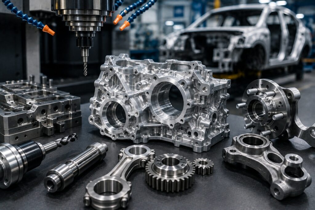
Precision CNC Manufacturing for Automotive Parts and Components The automotive industry requires components that meet demanding requirements for accuracy, repeatability, durability, and consistent production quality . From engine and transmission components to brackets, shafts, fixtures, prototypes, and custom tooling, manufacturers need reliable processes that can produce parts according to precise engineering specifications. CNC machining supports automotive component manufacturing by converting digital CAD designs into accurate physical parts using computer-controlled machining equipment. Depending on the component, manufacturers can use CNC milling, CNC turning, 3-axis, 4-axis, or 5-axis machining to produce complex geometries and precision features. At Polymach365 , we provide CNC milling, CNC turning, multi-axis machining, prototype manufacturing, low-volume production, custom CNC machining, and precision machined components. Therefore, CNC machining can support automotive projects from initial prototypes through production requirements. What Is CNC Machining in Automotive Manufacturing? CNC machining uses computer-controlled equipment to remove material from a workpiece according to programmed toolpaths. The process begins with a digital CAD model or engineering drawing. CAM software then converts the design into machining instructions that control the CNC machine. A typical workflow is: CAD Design → DFM Review → CAM Programming → CNC Machining → Inspection → Finishing → Finished Component As a result, manufacturers can produce automotive components with repeatable dimensions and controlled machining processes. Why Is CNC Machining Important for Automotive Parts? Automotive components often contain features that require precise manufacturing. These may include: Precision holes Shafts Threads Mounting surfaces Pockets Slots Curved profiles Complex contours Mating surfaces Therefore, CNC machining can provide the flexibility required for manufacturing both simple and complex automotive components. 1.Supports Automotive Prototyping Before a new automotive component enters production, engineers often need prototypes for testing and validation. CNC machining can manufacture functional prototypes directly from CAD designs. These prototypes can be used to evaluate: Fit Assembly Dimensions Clearances Strength Function Surface finish Therefore, CNC machining can help engineers identify design problems before committing to larger production quantities. A typical development process is: CAD Design → CNC Prototype → Testing → Design Modification → Production Consequently, manufacturers can improve designs before scaling production. 2. Produces Custom Automotive Components Not every automotive component is a standard catalog item. Manufacturers may require custom parts for: Vehicle development Motorsport Specialty vehicles Testing equipment Manufacturing machinery Restoration projects Automotive tooling CNC machining allows components to be produced according to specific CAD models, drawings, dimensions, and material requirements. As a result, manufacturers can produce parts that match the requirements of a particular vehicle or application. 3. CNC Milling for Automotive Components CNC milling is suitable for many automotive components that require pockets, holes, slots, flat surfaces, and complex profiles. Applications may include: Braces Mounting plates Housings Fixtures Engine-related components Tooling components Custom automotive parts Furthermore, multi-axis milling can provide access to multiple surfaces when a component contains complex geometry. Therefore, CNC milling provides considerable flexibility for automotive manufacturing. 4. CNC Turning for Automotive Parts CNC turning is particularly useful for cylindrical automotive components. Common examples include: Shafts Pins Bushings Spacers Sleeves Rollers Couplings Threaded components During CNC turning, the workpiece rotates while the cutting tool removes material. Consequently, turning can produce consistent cylindrical features and diameters for automotive applications. 5. 5-Axis CNC Machining for Complex Automotive Parts Some automotive components contain complex surfaces and features across multiple sides. 5-axis machining can provide additional flexibility when manufacturing these geometries. It can be useful for parts containing: Angled surfaces Complex contours Deep cavities Multi-sided features Difficult-to-access areas Therefore, 5-axis machining can reduce the need for multiple setups for suitable component designs. However, not every automotive part requires 5-axis machining. The appropriate process depends on the component’s geometry, tolerances, material, quantity, and production requirements. 6.Supports Low-Volume Automotive Production Automotive manufacturing does not always involve large production quantities. Engineers and specialty manufacturers may require small quantities for: Testing Validation Pilot production Replacement parts Engineering changes Specialty vehicles CNC machining can support one-off components and small production batches. Therefore, it can provide flexibility when high-volume manufacturing is unnecessary. 7.CNC Machining for Automotive Replacement Parts Automotive machinery and production equipment require regular maintenance. When a custom component becomes damaged or unavailable, manufacturers may need a replacement part. CNC machining can produce suitable replacement components using available: CAD files Engineering drawings Measurements Existing part specifications Common replacement components include: Shafts Bushings Braces Mounting components Fixtures Spacers Custom machine parts As a result, CNC machining can provide a flexible manufacturing option for specialized replacement components. 8. Automotive Tooling and Fixtures Automotive production depends heavily on tooling and fixtures. These components help position, hold, inspect, and manufacture production parts. CNC machining can produce: Assembly fixtures Inspection fixtures Drilling fixtures Jigs Mounting fixtures Custom tooling Production aids Therefore, CNC machining can support not only automotive components but also the equipment used to manufacture them. 9. Material Options for Automotive CNC Parts Material selection is an important consideration in automotive manufacturing. Depending on the application, CNC-machined components may be manufactured from materials such as: Aluminum Stainless steel Carbon steel Tool steel Brass Copper Titanium Engineering plastics Aluminum Aluminum offers low weight and good machinability, making it suitable for many automotive components and prototypes. Stainless Steel Stainless steel provides strength and corrosion resistance for demanding applications. Carbon Steel Carbon steel can provide strength and durability for various mechanical components. Engineering Plastics Materials such as Nylon, Delrin, PEEK, ABS, and Polycarbonate can be considered for applications where reduced weight or specific material properties are required. Therefore, the material should be selected according to the component’s mechanical, thermal, environmental, and functional requirements. Quality Control During Prototype Production Prototype components may require different inspection priorities compared with large production batches. For prototypes, manufacturers may focus heavily on: Design verification Critical dimensions Assembly fit Functional features Material Surface finish Therefore, prototype inspection can help engineers identify design or manufacturing issues before production quantities increase. 10. CNC Machining and Automotive Quality Control Automotive components often require consistent dimensions and reliable assembly. Therefore, quality control is an important part of CNC manufacturing. Inspection may include: Dimensional measurements Hole diameter