CNC Machining for Complex Parts: Challenges and Manufacturing Solutions
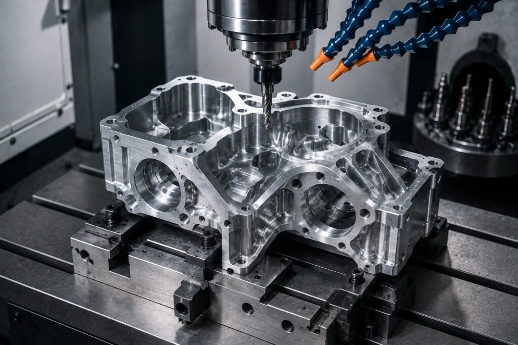
Precision CNC Manufacturing for Complex Components Manufacturing complex parts requires more than simply removing material from a workpiece. Components with deep cavities, tight tolerances, angled surfaces, intricate contours, and features across multiple faces can create significant machining challenges. CNC machining for complex parts provides manufacturers with a flexible solution for producing these components accurately and consistently. By combining advanced CNC equipment, appropriate tooling, CAM programming, workholding, and careful inspection, manufacturers can produce complex components for demanding applications. At Polymach365 , we provide CNC milling, CNC turning, 3-axis, 4-axis, and 5-axis machining, prototype manufacturing, low-volume production, custom CNC machining, and precision machined components. Therefore, choosing the right machining strategy from the beginning can help improve part quality while controlling production time and costs. What Are Complex CNC Machined Parts? Complex CNC machined parts contain geometries or manufacturing requirements that are more difficult to produce than conventional components. These parts may include: Deep cavities Angled surfaces Complex contours Thin walls Small holes Tight tolerances Multiple machining faces Internal features Curved surfaces Difficult-to-reach areas Complex 3D profiles For example, an aerospace component may contain several angled surfaces and curved profiles, while a mold component may require precise cavities, inserts, and fine details. Therefore, complex machining requires careful coordination between part design, CNC programming, tooling, workholding, machining parameters, and inspection . Why Is Complex CNC Machining Challenging? Several factors can make complex components difficult to manufacture. 1. Multiple Machining Setups A complex component may require access to several surfaces. With a conventional setup, the operator may need to reposition the workpiece multiple times. Every additional setup can introduce: Alignment errors Additional setup time Positioning variation Increased labor Longer production times Therefore, reducing unnecessary setups can improve both efficiency and consistency. Manufacturing Solution Multi-axis CNC machining can provide access to multiple surfaces without requiring as many repositioning operations. As a result, suitable 4-axis and 5-axis machining strategies can simplify the production of certain complex components. 2. Difficult-to-Reach Features Deep cavities, internal pockets, and angled surfaces can make tool access difficult. A conventional cutting tool may not reach the required feature effectively. Using an excessively long tool can also increase: Tool deflection Vibration Chatter Dimensional variation Tool wear Therefore, tool selection should be considered during the design and programming stages. Manufacturing Solution Manufacturers can select appropriate tool lengths, diameters, holders, and machining orientations. Furthermore, 5-axis machining can position the cutting tool at suitable angles for certain difficult-to-reach features. 3. Tight Machining Tolerances Some complex parts require very precise dimensions. However, maintaining tight tolerances across multiple features can become challenging because machining accuracy can be affected by: Machine condition Tool wear Material movement Temperature Workholding Tool deflection Machining parameters Therefore, manufacturers should identify critical tolerances before production begins. Manufacturing Solution A suitable process may include: CAD Review → DFM Analysis → CNC Programming → Controlled Machining → Inspection Consequently, manufacturers can focus quality-control efforts on the features that directly affect component performance. 4. Tool Deflection Tool deflection occurs when cutting forces cause the cutting tool to bend slightly during machining. This problem can become more noticeable when machining: Deep pockets Thin walls Hard materials Narrow features Long-reach geometries As a result, the finished feature may not match the intended CAD geometry precisely. Manufacturing Solution Manufacturers can reduce the risk of deflection by using: Appropriate tool diameters Shorter tools where possible Suitable cutting parameters Multiple machining passes Appropriate toolpaths Therefore, a well-planned machining strategy can improve dimensional consistency. 5. Thin Walls and Delicate Features Thin walls can deform under machining forces. Similarly, small ribs and delicate features can become damaged during aggressive material removal. Therefore, complex designs should consider the relationship between wall thickness and machining forces. Manufacturing Solution A manufacturer can use multiple lighter passes rather than removing large amounts of material in a single operation. Furthermore, suitable workloads can provide additional stability. As a result, the manufacturer can reduce deformation while maintaining the required geometry. 6. Complex Internal Cavities Internal cavities can be difficult because cutting tools may have limited access. Deep cavities can also create problems with: Chip evacuation Coolant access Tool deflection Heat generation Visibility Therefore, internal geometry should be designed with manufacturing ability in mind. Manufacturing Solution Appropriate tool selection, machining orientation, chip evacuation, and staged roughing and finishing operations can improve cavity machining. Consequently, manufacturers can produce deeper and more detailed features more efficiently. 7. Surface Finish Requirements Complex parts may contain surfaces that require specific finishes. However, difficult tool access can make consistent finishing challenging. Surface quality can be influenced by: Tool condition Feed rate Spindle speed Toolpath Material Machine rigidity Tool geometry Therefore, finishing operations should be planned separately from aggressive roughing operations. Manufacturing Solution A typical approach is: Roughing → Semi-Finishing → Finishing → Inspection This strategy allows manufacturers to remove material efficiently first and then focus on achieving the required surface condition. 8. Material Selection The material can significantly affect machining difficulty. For example, aluminum is generally easier to machine than many harder alloys, while titanium and some hardened steels may require more specialized machining strategies. Common materials for complex CNC components include: Aluminum Stainless steel Carbon steel Tool steel Brass Copper Titanium Engineering plastics Therefore, material selection should consider both the component’s performance requirements and its machinability. 9. Complex CAD Geometry A highly detailed CAD model does not automatically mean that the component can be manufactured efficiently. Designs may contain features that are: Too deep Too narrow Too small Difficult to access Expensive to machine Therefore, engineers should review manufacturing ability before releasing the design for production. Manufacturing Solution Design for Manufacture (DFM) can identify potential machining problems before production. A DFM review may evaluate: Tool accessibility Internal radii Wall thickness Hole sizes Tolerances Setup requirements Material Machining orientation Consequently, early design improvements can reduce manufacturing difficulties later. 10. 5-Axis CNC Machining for Complex Parts 5-axis machining is particularly useful when a component contains multiple surfaces, angled features, and complex contours. Unlike conventional 3-axis machining, 5-axis equipment can provide additional movement between the cutting tool and
CNC Machining Quality Control: Inspection Methods and Best Practices
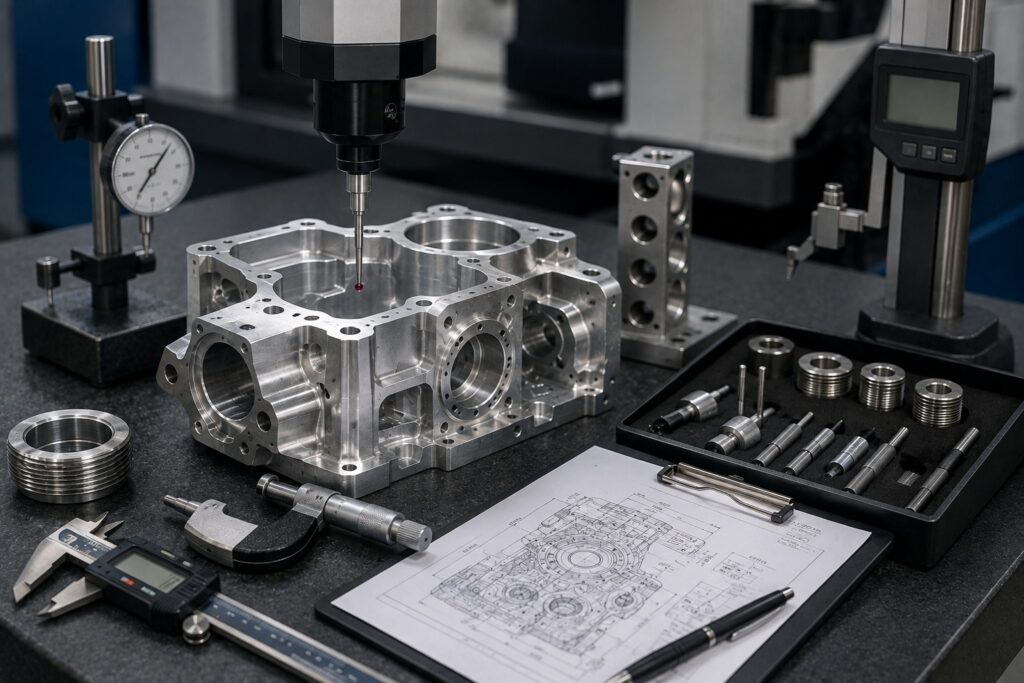
A Complete Guide to Maintaining Accuracy and Consistency in CNC Manufacturing Quality control is a critical part of CNC machining. Even when a component is produced using advanced CNC equipment, the finished part still needs to meet the required dimensions, tolerances, geometry, surface finish, and material specifications. A reliable quality-control process helps manufacturers identify dimensional errors, tool wear, machine problems, surface defects, and other issues before they affect larger production batches. At Polymach365, we support CNC milling, CNC turning, 3-axis, 4-axis, and 5-axis machining, prototype manufacturing, low-volume production, custom CNC parts, mold components, and precision machined components. Therefore, understanding CNC inspection methods can help engineers and manufacturers establish clearer quality requirements for their parts. What Is CNC Machining Quality Control? CNC machining quality control is the process of checking whether a manufactured component meets its specified engineering requirements. Depending on the part, quality control may evaluate: Dimensions Tolerances Hole diameters Hole positions Flatness Parallelism Perpendicularity Roundness Surface finish Threads Material requirements Visual appearance Therefore, quality control should begin with understanding the design requirements and continue throughout the manufacturing process. Why Is Quality Control Important in CNC Machining? A small dimensional error can prevent a component from fitting correctly into an assembly. For example, an incorrectly positioned hole may cause: Assembly problems Misalignment Excessive vibration Premature wear Component failure Similarly, an unsuitable surface finish can affect friction, sealing, appearance, or wear. Consequently, quality inspection helps manufacturers verify that the finished component performs according to its intended requirements. 1. First Article Inspection First Article Inspection (FAI) involves inspecting an initial manufactured component before continuing with larger production quantities. The purpose is to verify that the manufacturing process can produce the required specifications. A first article inspection may check: Critical dimensions Hole locations Material Surface finish Geometric tolerances Threads Overall part geometry Therefore, identifying problems during the first inspection can help prevent the same issue from affecting an entire production batch. 2. In-Process Inspection Quality control does not need to happen only after machining. In-process inspection checks important features while manufacturing is still underway. This can help identify: Tool wear Dimensional drift Incorrect offsets Machine problems Workpiece movement Unexpected machining conditions For example, if a cutting tool begins wearing during a production run, measurements may reveal a gradual dimensional change. Consequently, manufacturers can make adjustments before producing a large number of nonconforming components. 3. Final Inspection Final inspection takes place after the component has completed the required machining and finishing processes. The inspection process may verify: Overall dimensions Critical tolerances Surface finish Hole sizes Thread dimensions Geometric features Visual quality Therefore, final inspection provides confirmation that the finished component meets the applicable specifications before delivery or assembly. Common CNC Inspection Methods Different components require different inspection methods. 1. Vernier Calipers Calipers are commonly used for general dimensional measurements. They can measure: Outside dimensions Inside dimensions Depths Step dimensions Therefore, calipers are useful for quick dimensional checks. However, they may not be suitable for every high-precision measurement. 2. Micrometers Micrometers provide more precise dimensional measurements than general-purpose calipers. They can be used to inspect: Shaft diameters Thickness Outside dimensions Precision cylindrical features Consequently, micrometers are useful when tighter dimensional requirements need to be verified. 3. Height Gauges Height gauges can measure the position of features relative to a reference surface. They are useful for checking: Hole locations Heights Steps Reference dimensions Therefore, height gauges can support dimensional and positional inspection. 4. Bore Gauges Bore gauges are useful for measuring internal diameters. They can help inspect: Holes Cylindrical bores Internal diameters Consequently, bore inspection can be particularly important for components that must fit accurately with shafts or other mating parts. 5. Coordinate Measuring Machines A Coordinate Measuring Machine (CMM) can measure complex geometries and multiple dimensional characteristics. CMM inspection can evaluate: Dimensions Hole positions Geometric relationships Contours Flatness Parallelism Perpendicularity Therefore, CMMs can be particularly useful for complex precision components with multiple critical features. 6. Surface Roughness Measurement Some components require a specific surface roughness. Surface inspection can evaluate characteristics such as Ra, depending on the applicable specification. Surface finish requirements can be important for: Sealing surfaces Sliding components Bearing surfaces Mating components Visible parts Therefore, surface roughness should be measured when it is a critical functional requirement. 7. Thread Inspection Threads must meet the required size and profile to ensure proper assembly. Inspection may involve suitable gauges or measurement equipment depending on the thread specification. Therefore, thread inspection is important for components that connect with bolts, fasteners, fittings, or other threaded parts. Dimensional Accuracy vs Geometric Accuracy CNC quality control involves more than checking basic dimensions. Dimensional Accuracy Dimensional inspection verifies measurements such as: Length Width Thickness Diameter Hole size Geometric Accuracy Geometric inspection evaluates relationships between surfaces and features. Examples include: Flatness Parallelism Perpendicularity Position Concentricity Roundness Therefore, a component can have correct basic dimensions while still failing an important geometric requirement. CNC Quality Control for Different Processes CNC Milling Milled components may require inspection of: Pocket dimensions Hole locations Flatness Slot widths Surface profiles Overall dimensions Therefore, inspection should focus on the features that affect assembly and function. CNC Turning Turned components commonly require checks for: Diameter Length Roundness Concentricity Threads Surface finish Consequently, appropriate measurement methods should be selected according to the component’s geometry. Quality Control for 5-Axis CNC Machining Complex 5-axis components can contain features across multiple surfaces. Therefore, inspection may need to verify: Multi-sided features Angled surfaces Complex contours Hole positions Geometric relationships For complex components, advanced measurement methods can help verify the relationship between different surfaces and features. As a result, inspection planning should be considered alongside the machining strategy. How Tool Wear Affects Quality Cutting tools gradually wear during machining. As wear increases, manufacturers may observe: Dimensional changes Poor surface finish Increased cutting forces Burr formation Tool breakage Therefore, monitoring tool condition is an important part of CNC quality control. Regular tool inspection and appropriate replacement intervals can help maintain production consistency. Machine Calibration and Quality The condition and calibration of the CNC machine can also
CNC Machining Surface Finishes: Types, Options, and Applications
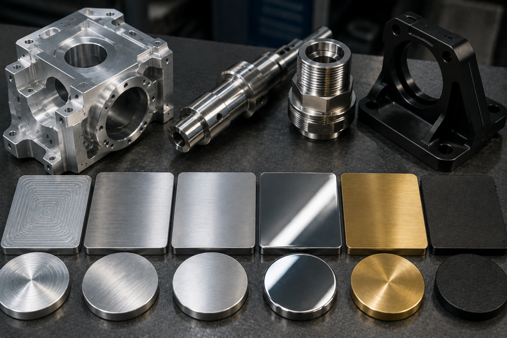
A Complete Guide to Choosing the Right Surface Finish for CNC Machined Parts Surface finish is an important part of CNC machining because it affects the appearance, functionality, durability, friction, corrosion resistance, and overall performance of a machined component. A part may have accurate dimensions, but the wrong surface finish can still affect how it performs in an assembly or operating environment. Therefore, choosing the right CNC machining surface finish should be considered during the design and manufacturing stages. At Polymach365, we provide CNC milling, CNC turning, 3-axis, 4-axis, and 5-axis machining, prototype manufacturing, low-volume production, custom CNC machining, and precision machined components. Understanding different surface finish options can help engineers select the most suitable solution for their parts. What Is CNC Machining Surface Finish? CNC machining surface finish refers to the texture and condition of a component’s surface after machining and any additional finishing processes. The final surface can be influenced by: Cutting tool condition Feed rate Spindle speed Material Toolpath Depth of cut Machining process Tool geometry Finishing operations Surface finish is commonly described using surface roughness, often represented by parameters such as Ra (average surface roughness). However, surface roughness is only one aspect of surface quality. Depending on the application, manufacturers may also consider appearance, coating, hardness, corrosion resistance, and wear resistance. Why Does Surface Finish Matter in CNC Machining? The required finish depends on how the component will be used. A surface finish can influence: Appearance Visible components may require a smoother and more uniform appearance. Friction Moving components may require a suitable surface texture to control friction and wear. Corrosion Resistance Some finishing processes can provide additional protection against environmental exposure. Wear Resistance Components exposed to repeated movement or contact may benefit from appropriate finishing treatments. Assembly Mating surfaces may require controlled surface characteristics for proper fitting and operation. Sealing Certain sealing surfaces require appropriate roughness to support reliable contact. Therefore, surface finish should be selected according to the function of the component rather than simply choosing the smoothest possible option. CNC Machining Surface Finish Options There are several ways to achieve the desired surface condition. 1. As-Machined Finish An as-machined finish is the surface produced directly by the CNC machining process without an additional cosmetic finishing operation. The final appearance depends on: Cutting tool Feed rate Material Machining strategy Toolpath Machine condition Therefore, as-machined finishing can be a practical choice when appearance is not the primary concern. Common Applications Internal machine components Fixtures Structural parts Functional prototypes Hidden components Moreover, avoiding unnecessary finishing can help control manufacturing costs. 2. Smooth CNC Machined Finish A finishing pass can improve the surface quality of a CNC machined component. Manufacturers may adjust: Feed rate Cutting depth Toolpath Tool geometry Cutting speed A suitable finishing operation can reduce visible tool marks and improve surface consistency. Therefore, a smoother machined finish may be appropriate for components where surface quality is important but additional coating is unnecessary. 3. Polishing Polishing removes or reduces surface imperfections to create a smoother and more refined appearance. It can be used when the component requires: Smooth surfaces Improved appearance Reduced surface roughness Decorative finishing Polishing can be applied to suitable metals and other materials depending on their properties. Consequently, polished CNC components are often selected for visible or presentation-focused applications. 4. Brushing Brushing creates a consistent directional texture across the surface. It is commonly used when manufacturers want a uniform appearance without creating a highly reflective polished surface. Brushed finishes can be useful for: Enclosures Consumer products Panels Visible machine components Therefore, brushing can combine functional surface treatment with an attractive appearance. 5. Anodizing Anodizing is commonly used for aluminum components. It can improve: Surface durability Corrosion resistance Appearance Surface hardness Anodized aluminum is widely used in applications where both appearance and surface protection are important. Common applications include: Electronic housings Automotive components Aerospace parts Consumer products Machine components Therefore, anodizing can be a useful finishing option for CNC-machined aluminum parts. 6. Powder Coating Powder coating applies a protective coating to the component’s surface. It can provide: Corrosion protection Surface durability Color options Improved appearance Therefore, powder coating can be useful for components that require a durable external coating. However, designers should consider coating thickness when specifying critical dimensions or mating surfaces. 7. Plating Plating deposits a layer of another material onto the surface of a component. Depending on the application, plating can improve: Corrosion resistance Wear resistance Electrical properties Surface appearance Therefore, plating can be considered when the component requires properties beyond those provided by the base material. 8. Heat Treatment Heat treatment changes the properties of suitable metal components through controlled heating and cooling. Depending on the material and process, heat treatment can improve: Hardness Strength Wear resistance Dimensional stability Therefore, heat treatment may be appropriate for CNC components exposed to demanding mechanical conditions. CNC Surface Finish for Different Materials Different materials respond differently to machining and finishing processes. Aluminum Aluminum is highly machinable and supports several finishing options, including: As-machined Anodizing Polishing Brushing Powder coating Therefore, aluminum provides considerable flexibility when appearance and corrosion resistance are important. Stainless Steel Stainless steel can be machined and subsequently finished using processes such as: Polishing Brushing Passivation Other application-specific treatments Therefore, stainless steel can provide both functional performance and a wide range of appearance options. Brass Brass can provide an attractive natural appearance and can also be polished or otherwise finished depending on the application. It is commonly considered for: Fittings Decorative components Connectors Precision mechanical parts Titanium Titanium may require specialized finishing depending on the intended application. Because titanium is often selected for demanding environments, the finishing process should be compatible with the component’s mechanical and environmental requirements. Surface Finish in CNC Milling CNC milling can produce different surface characteristics depending on the machining strategy. Surface quality can be affected by: Cutter selection Tool diameter Toolpath direction Stepover Feed rate Spindle speed Finishing passes For example, a roughing operation prioritizes material removal, while a finishing operation focuses more heavily on dimensional accuracy
How CNC Machining Works: From CAD Design to Finished Part
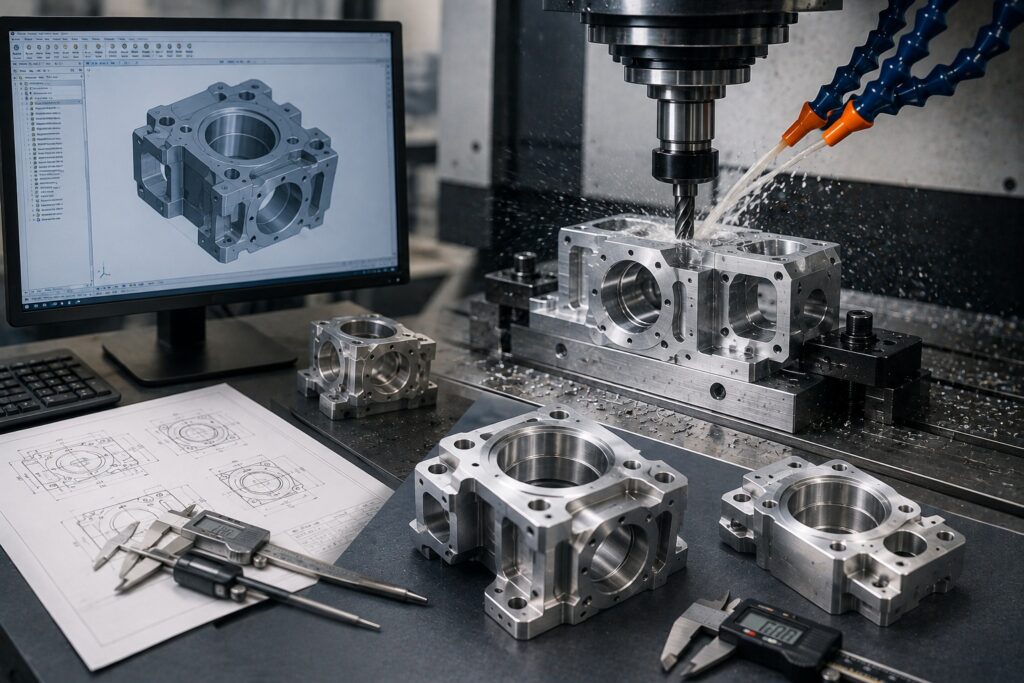
A Complete Guide to the CNC Machining Process CNC machining is one of the most widely used manufacturing methods for producing accurate metal and plastic components. From prototypes and custom parts to low-volume production and complex industrial components, CNC machining can transform a digital design into a precise physical part. But how does CNC machining actually work? The process involves several stages, starting with a CAD model and ending with an inspected, finished component. Each stage affects the accuracy, quality, cost, and production time of the final part. At Polymach365, we support CNC milling, CNC turning, 3-axis, 4-axis, and 5-axis machining, prototype manufacturing, low-volume production, custom CNC components, and precision machined parts. What Is CNC Machining? CNC stands for Computer Numerical Control. CNC machining uses computer-controlled equipment to remove material from a workpiece according to programmed instructions. Instead of manually controlling the cutting tool, the machine follows a digital program that controls movements along different axes. Depending on the machine, CNC equipment can perform operations such as: Milling Turning Drilling Boring Threading Tapping Reaming Contouring Pocketing Therefore, CNC machining can produce components with accurate dimensions and repeatable features. How Does CNC Machining Work? A typical CNC manufacturing process follows this sequence: CAD Design → Design Review → CAM Programming → Machine Setup → Material Preparation → CNC Machining → Inspection → Finishing → Finished Part Each stage has an important role in producing the final component. 1. Create the CAD Design The CNC machining process begins with a Computer-Aided Design (CAD) model. Engineers use CAD software to create a detailed representation of the component. The model defines the geometry and dimensions required for manufacturing. A CAD design may include: Overall dimensions Holes Slots Pockets Threads Curves Contours Internal features Mounting locations Engineering drawings may also provide information about: Tolerances Surface finishes Materials Critical dimensions Therefore, an accurate CAD model provides the foundation for the entire machining process. 2. Review the Design for Manufacturability Before production begins, the design should be reviewed to determine whether it can be manufactured efficiently. This stage is often referred to as Design for Manufacturability (DFM). Manufacturers may evaluate: Tool accessibility Internal corner radii Wall thickness Hole sizes Deep cavities Tight tolerances Workholding requirements Material selection For example, a very deep pocket may require a long cutting tool, which can increase vibration and reduce machining efficiency. Therefore, identifying potential manufacturing problems before machining can reduce unnecessary production delays and costs. 3. Convert the CAD Model into a CAM Program The CAD model describes what the part should look like. However, the CNC machine needs specific instructions explaining how to manufacture it. This is where Computer-Aided Manufacturing (CAM) software is used. CAM software generates toolpaths that determine how the cutting tool will move. The program can define: Tool movements Cutting directions Spindle speeds Feed rates Cutting depths Tool changes Machining sequences The resulting instructions are then converted into machine-readable CNC code. Consequently, CAM programming connects the digital design with the physical machining process. 4. Select the CNC Machine The appropriate CNC machine depends on the component’s geometry and manufacturing requirements. Common CNC machines include: 3-Axis CNC Machines These machines move the cutting tool along three primary axes. They are suitable for many straightforward components such as: Plates Brackets Housings Fixtures Mounting components 4-Axis CNC Machines A fourth axis allows additional rotational movement. Therefore, 4-axis machining can provide greater access to multiple surfaces. 5-Axis CNC Machines 5-axis machines can move the tool and workpiece across multiple axes. They are particularly useful for: Complex contours Angled surfaces Multi-sided components Deep features Complex tooling CNC Lathes CNC turning machines rotate the workpiece while cutting tools remove material. They are commonly used for: Shafts Pins Bushings Sleeves Rollers Spacers Therefore, selecting the right CNC machine is essential for efficient production. 5. Select the Material The next step is preparing the correct workpiece material. CNC machining can process many metals and engineering plastics. Common materials include: Aluminum Stainless steel Carbon steel Tool steel Brass Copper Titanium ABS Nylon Delrin Polycarbonate PEEK Material selection depends on the component’s: Strength requirements Weight Temperature exposure Corrosion resistance Wear resistance Electrical properties Cost Application Therefore, material selection should be considered during the design stage rather than after the CAD model is completed. 6. Secure the Workpiece Before machining begins, the material must be securely positioned in the CNC machine. This process is known as workholding. Common workholding methods include: Vises Clamps Fixtures Chucks Custom workholding systems The workpiece must remain stable during cutting. Poor workholding can cause: Vibration Part movement Dimensional errors Surface defects Component deformation Therefore, proper workholding is essential for maintaining machining accuracy. 7. Install and Set Up Cutting Tools Different machining operations require different cutting tools. Common CNC tools include: End mills Drills Ball-nose cutters Reamers Taps Boring tools Face mills The manufacturer selects tooling according to the material, geometry, feature size, and machining operation. For example, an end mill may be used for pockets and contours, while a drill can create holes. Consequently, correct tool selection affects machining efficiency, tool life, surface finish, and dimensional accuracy. 8. CNC Machine Removes Material Once the machine is set up, the CNC program controls the machining operation. The cutting tool removes material according to the programmed toolpath. Depending on the component, machining may involve: Roughing Roughing removes larger amounts of material quickly. Semi-Finishing Semi-finishing brings the component closer to its final dimensions. Finishing Finishing operations remove smaller amounts of material to achieve the required dimensions and surface quality. Therefore, complex components may require multiple machining operations before they reach their final form. 9. Monitor the Machining Process CNC machining is automated, but monitoring remains important. Manufacturers may monitor: Tool wear Cutting conditions Machine vibration Coolant flow Material behavior Dimensional changes Tool wear can gradually affect component dimensions and surface finish. Therefore, monitoring tool condition is particularly important during longer production runs. 10. Inspect the Finished Component After machining, the finished component is inspected against the applicable specifications. Inspection may include: Overall dimensions Hole diameters
CNC Machining for Replacement Parts: Benefits and Applications
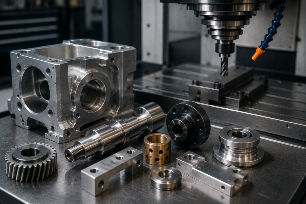
Reliable Custom Manufacturing for Replacement Components When an essential machine component fails, finding the correct replacement part quickly can be challenging. Original components may be discontinued, unavailable, difficult to source, or subject to long lead times. CNC machining for replacement parts provides manufacturers and maintenance teams with a flexible way to produce custom components according to specific dimensions and application requirements. Instead of waiting for a standard replacement to become available, businesses can manufacture a component from a CAD model, engineering drawing, existing sample, or measured specifications, depending on the project requirements. At Polymach365, we provide CNC milling, CNC turning, 3-axis, 4-axis, and 5-axis machining, prototype manufacturing, low-volume production, custom CNC parts, and precision machining solutions. These capabilities can support replacement-part requirements across industrial machinery, automation, automotive, tooling, and other applications. What Are CNC Replacement Parts? CNC replacement parts are custom-machined components manufactured to replace an original or damaged component. These parts may be required when the original component is: Worn out Damaged Discontinued Difficult to source No longer supported Available only with long lead times No longer manufactured Therefore, CNC machining can provide an alternative manufacturing route for components that are not readily available through conventional suppliers. Common CNC replacement parts include: Shafts Bushings Pins Brackets Housings Couplings Spacers Mounting plates Rollers Fixtures Machine components Custom tooling Why Use CNC Machining for Replacement Parts? CNC machining provides several advantages when a replacement component needs to match an existing part. 1. Manufacture Parts to Specific Dimensions Replacement components often need to fit directly into an existing assembly. Therefore, dimensional accuracy is particularly important. CNC machining can manufacture features such as: Precise holes Shafts Threads Slots Pockets Mounting surfaces Cylindrical features As a result, manufacturers can produce replacement components according to defined engineering specifications. 2. Reduce Equipment Downtime Unexpected component failure can interrupt production. When a critical part is unavailable, equipment may remain inactive until a replacement arrives. CNC machining can provide a manufacturing option for certain custom replacement components, helping businesses address urgent requirements more efficiently. However, actual production and delivery times depend on factors such as: Part complexity Material availability Quantity Tolerances Finishing requirements Machine availability Therefore, providing complete technical information early can help streamline the manufacturing process. 3. Manufacture Discontinued Components Older machinery may use components that are no longer produced by the original manufacturer. Replacing the entire machine simply because one component is unavailable may not be practical. Instead, a replacement component can potentially be manufactured based on available technical information. This may include: Original CAD files Engineering drawings Technical specifications Existing samples Measured dimensions Consequently, CNC machining can help extend the useful life of older equipment when suitable replacement manufacturing is technically feasible. 4. Support One-Off and Low-Volume Requirements Replacement parts are often needed in very small quantities. For example, a business may require only: One shaft Two bushings A replacement bracket A small batch of machine components CNC machining can support one-off and low-volume manufacturing without requiring large production quantities. Therefore, it can be particularly useful for specialized or infrequently replaced components. 5. Manufacture Custom Components Not every replacement component has a standard equivalent. Some machines use custom-designed parts that cannot be purchased from regular component suppliers. CNC machining allows manufacturers to reproduce components according to specific requirements. Therefore, custom machining can support replacement parts with: Unique dimensions Custom mounting patterns Special holes Complex profiles Specific materials Tight tolerances CNC Milling for Replacement Parts CNC milling is suitable for replacement components with flat surfaces, pockets, holes, slots, and complex profiles. Common replacement milled parts include: Brackets Mounting plates Machine housings Fixtures Covers Tooling components Custom mechanical parts Furthermore, 4-axis and 5-axis machining can provide access to multiple surfaces when a replacement component has more complex geometry. CNC Turning for Replacement Parts CNC turning is particularly suitable for rotational replacement components. Typical examples include: Shafts Bushings Pins Rollers Sleeves Spacers Couplings Threaded components Because the workpiece rotates during machining, CNC turning can produce consistent cylindrical features and diameters. Consequently, it can be an effective manufacturing method for many mechanical replacement components. 5-Axis CNC Machining for Complex Replacement Components Some replacement parts have features across multiple surfaces or contain difficult-to-access geometry. In suitable applications, 5-axis CNC machining can provide greater flexibility for these components. It can be useful for: Complex contours Angled surfaces Deep cavities Multi-sided components Specialized tooling Complex machine components Therefore, selecting the appropriate machining process is important when reproducing complex replacement parts. Materials for CNC Replacement Parts The replacement material should be selected according to the original component’s function and operating environment. Common CNC machining materials include: Aluminum Aluminum provides low weight and good machinability. Therefore, it can be suitable for lightweight brackets, housings, fixtures, and machine components. Stainless Steel Stainless steel offers strength and corrosion resistance. Consequently, it can be useful for components operating in demanding environments. Carbon Steel Carbon steel provides strength and durability for many industrial applications. Brass Brass offers good machinability and corrosion resistance, making it suitable for fittings, bushings, connectors, and other components. Copper Copper is useful when electrical or thermal conductivity is important. Titanium Titanium provides a high strength-to-weight ratio and corrosion resistance, although it requires appropriate machining strategies. Engineering Plastics Materials such as ABS, Nylon, Delrin, Polycarbonate, PEEK, and PTFE can be considered when low weight, electrical insulation, chemical resistance, or low friction is required. Therefore, material selection should always consider the component’s original function and operating conditions. How to Manufacture a CNC Replacement Part A typical replacement-part workflow can include several stages. Step 1: Identify the Failed Component Determine the component’s function and how it interacts with the surrounding assembly. Step 2: Collect Technical Information Provide an available: CAD file Engineering drawing Dimensions Material specification Existing component Photographs Technical requirements The more complete the information, the easier it is to establish the manufacturing requirements. Step 3: Review the Design The component can be evaluated for: Manufacturability Tolerances Material Tool access Workholding Machining process Step 4: Select the CNC Process Depending on the geometry, manufacturers may
How CNC Machining Supports Just-in-Time Manufacturing
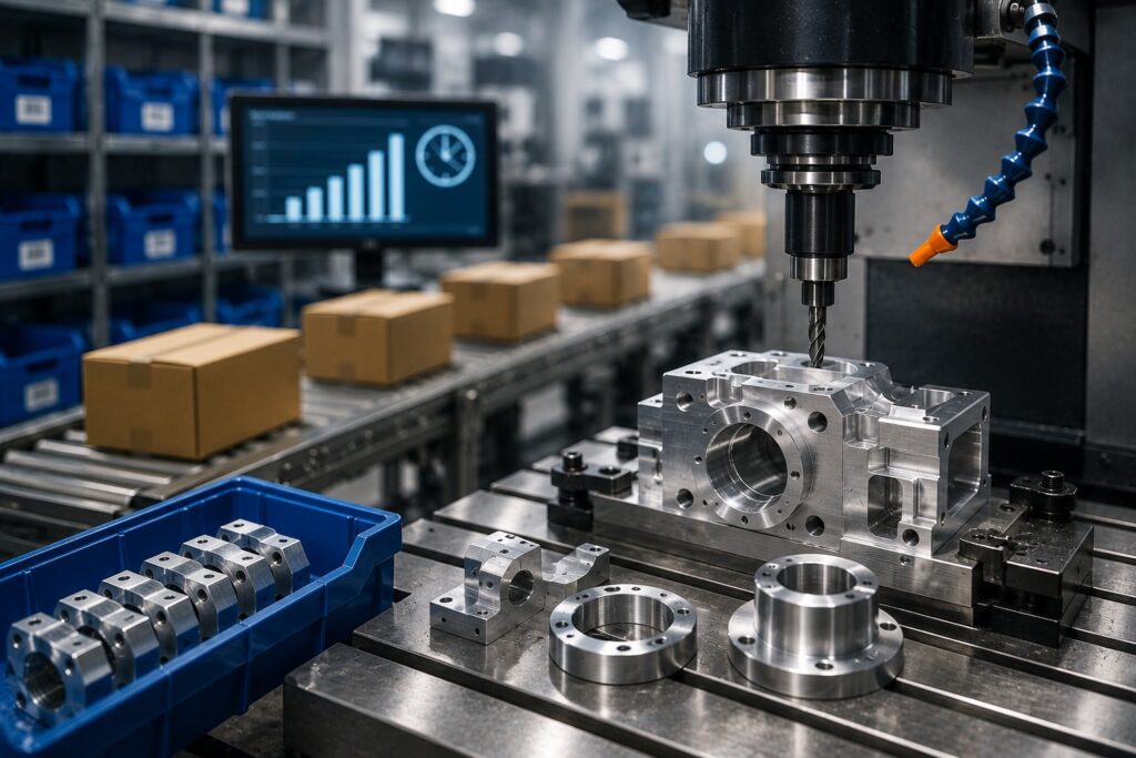
Improving Production Flexibility, Inventory Control, and Delivery Modern manufacturers constantly look for ways to reduce inventory, shorten production lead times, control costs, and respond quickly to changing customer demand. Just-in-Time (JIT) manufacturing addresses these challenges by producing components when they are needed instead of maintaining unnecessarily large inventories. CNC machining can play an important role in this approach. With digital CAD-based production, automated machining, repeatable processes, and flexible manufacturing capabilities, CNC machining allows businesses to produce custom components according to actual production requirements. At Polymach365, we provide CNC milling, CNC turning, 3-axis, 4-axis, and 5-axis machining, prototype manufacturing, low-volume production, custom CNC parts, and precision machining solutions. These capabilities can support manufacturers that need flexible production without relying on excessive component inventory. What Is Just-in-Time Manufacturing? Just-in-Time manufacturing is a production strategy in which materials and components are produced or delivered close to the time they are required. Instead of manufacturing large quantities and storing them for long periods, businesses aim to synchronize production with actual demand. A simplified JIT workflow looks like: Customer Demand → Production Planning → Component Manufacturing → Assembly → Delivery Therefore, manufacturers can reduce unnecessary inventory while maintaining a responsive production process. Why Is CNC Machining Important for JIT Manufacturing? CNC machining is well suited to flexible manufacturing because machines can produce different components by changing the digital program, tooling, and setup. Unlike processes that require dedicated tooling for every new component, CNC machining can often move between different designs using the appropriate CNC program. As a result, manufacturers can produce: Custom components Replacement parts Small batches Prototype parts Production components Machine components Tooling and fixtures Consequently, CNC machining can support production environments where component requirements change frequently. 1. Reduces the Need for Large Inventories Maintaining a large inventory of spare parts and components can tie up capital and require additional storage space. JIT manufacturing aims to reduce this dependency by producing parts closer to when they are required. CNC machining can support this approach by manufacturing components according to current production requirements. For example, instead of storing thousands of specialized replacement components, a manufacturer may maintain the digital CAD file and manufacture the required quantity when demand occurs. Therefore: Digital Inventory → Manufacturing on Demand → Reduced Physical Inventory This approach can be particularly useful for custom or low-demand components. 2. Supports Low-Volume Production JIT manufacturing does not always require large production runs. Businesses may need only a small number of components at a particular time. CNC machining is suitable for: One-off components Small batches Short production runs Replacement parts Engineering components Specialized industrial parts Therefore, manufacturers can produce closer to actual demand rather than committing to unnecessarily large quantities. 3. Shortens the Path from Design to Production Traditional manufacturing workflows can involve several stages between product design and physical production. Digital CNC manufacturing can simplify this process. A typical workflow is: CAD Design → Manufacturing Review → CNC Programming → Machining → Inspection → Delivery As a result, manufacturers can move from a digital design to a physical component through a streamlined process. This flexibility can be valuable when production schedules change unexpectedly. 4. Supports On-Demand Manufacturing One of the key principles of JIT manufacturing is producing components when they are needed. CNC machining can support on-demand production for custom and specialized components. For example, a manufacturer may require: Replacement machine parts Custom brackets Shafts Bushings Fixtures Tooling components Mold components Instead of storing every possible component, businesses can maintain the required digital designs and manufacture parts according to demand. Therefore, CNC machining can function as an important part of an on-demand manufacturing strategy. 5. Makes Production Changes Easier Manufacturing requirements can change because of: Customer orders Product modifications Engineering changes Supply chain disruptions Market demand Replacement requirements CNC machining provides flexibility because production instructions can be updated digitally. When a component design changes, manufacturers can modify the CAD model and CNC program before producing the next batch. Consequently, CNC machining can support manufacturers that need to respond quickly to engineering or production changes. 6. Supports Prototype-to-Production Manufacturing JIT manufacturing is not limited to established production parts. Product development teams also need prototypes, testing components, and small production batches. CNC machining can support the transition through: Prototype → Testing → Design Improvement → Low-Volume Production → Production Therefore, manufacturers can use CNC machining throughout different stages of product development. This can reduce the need to change manufacturing methods unnecessarily during early development. 7. Reduces Overstock and Obsolescence Excess inventory can become obsolete when: Product designs change Components are redesigned Customer requirements change Equipment is upgraded Products are discontinued JIT manufacturing reduces this risk by limiting unnecessary stock. CNC machining can support this strategy by producing specialized components closer to the time of use. As a result, manufacturers can reduce the amount of physical inventory that may become outdated. 8. Supports Custom Replacement Parts Industrial machinery often requires replacement components that are not readily available as standard products. Examples include: Shafts Bushings Brackets Couplings Mounting plates Machine components Fixtures Custom tooling When an original component becomes unavailable, CNC machining can reproduce a replacement part based on an existing drawing, CAD model, or suitable engineering specifications. Therefore, CNC machining can help manufacturers reduce equipment downtime while avoiding unnecessary stockpiling of replacement parts. 9. CNC Milling for JIT Manufacturing CNC milling is suitable for many custom components used in industrial production. Milling can manufacture: Brackets Housings Plates Fixtures Mounts Machine components Mold components Custom tooling Furthermore, CNC milling can accommodate different component geometries and production quantities. Therefore, it can support JIT manufacturing when businesses need flexible production of custom milled components. 10. CNC Turning for JIT Manufacturing CNC turning is ideal for rotational components. Common examples include: Shafts Pins Bushings Rollers Sleeves Spacers Couplings Threaded components Because CNC turning can produce different component designs through programmed machining operations, it can support production environments where demand varies. Consequently, manufacturers can produce rotational components according to actual requirements. 11. 5-Axis CNC Machining for Complex Components Some JIT
CNC Machining for Custom Metal Parts: Process, Materials, and Applications
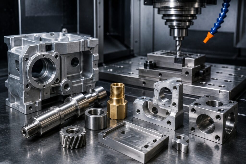
Precision CNC Manufacturing for Custom Metal Components CNC machining for custom metal parts provides manufacturers with a reliable way to produce components with precise dimensions, complex geometries, and repeatable quality. From prototypes and replacement components to low-volume production and industrial parts, CNC machining can accommodate a wide range of manufacturing requirements. Unlike standard off-the-shelf components, custom CNC machined parts are manufactured according to specific CAD models, engineering drawings, dimensions, tolerances, materials, and application requirements. At Polymach365, we provide CNC milling, CNC turning, 3-axis, 4-axis, and 5-axis machining, prototype manufacturing, low-volume production, and custom CNC machining solutions for manufacturers, engineers, and product developers. What Is CNC Machining for Custom Metal Parts? CNC machining uses computer-controlled equipment to remove material from a metal workpiece until it reaches the required shape and dimensions. The process begins with a digital CAD model. Manufacturing software converts the design into machine instructions, and CNC equipment follows the programmed toolpaths to cut the material. Therefore, CNC machining can produce custom components with features such as: Holes Slots Pockets Threads Contoured surfaces Internal cavities Mounting features Precision bores Complex profiles As a result, manufacturers can create custom metal parts that match specific functional and assembly requirements. CNC Machining Process for Custom Metal Parts Producing a custom metal component involves several important stages. 1. CAD Design The process starts with a 2D drawing or 3D CAD model containing the required dimensions and geometry. The design should include important information such as: Material Dimensions Tolerances Surface finish Thread specifications Critical features Therefore, a detailed CAD model helps establish clear manufacturing requirements. 2. Design and Manufacturing Review Before machining begins, the component should be evaluated for manufacturability. This review can identify potential issues involving: Tool accessibility Thin walls Deep pockets Internal corner radii Tight tolerances Workholding Machining orientation Consequently, addressing these issues before production can help reduce machining difficulties and unnecessary costs. 3. Material Selection The correct metal should be selected according to the component’s application. Important considerations include: Strength Weight Hardness Corrosion resistance Temperature resistance Wear resistance Machinability Cost Therefore, material selection should take place before finalizing the machining strategy. 4. CNC Programming The CAD design is converted into machine-readable instructions. The CNC program determines: Tool movement Cutting direction Spindle speed Feed rate Cutting depth Machining sequence As a result, the machine can follow a controlled and repeatable process. 5. CNC Machining The selected metal workpiece is securely positioned in the CNC machine. Depending on the component, manufacturers may use: CNC milling CNC turning 3-axis machining 4-axis machining 5-axis machining Therefore, the machining process can be selected according to the geometry and manufacturing requirements of the part. 6. Inspection and Finishing After machining, critical dimensions and features can be inspected according to the project requirements. Additional finishing processes may also be required, depending on the application. These can include: Deburring Polishing Anodizing Powder coating Plating Heat treatment Consequently, the finished component can be prepared for assembly or final application. CNC Milling for Custom Metal Parts CNC milling uses rotating cutting tools to remove material from a stationary workpiece. It is suitable for manufacturing components with: Flat surfaces Pockets Slots Holes Contours Complex profiles Multiple machined faces Common CNC Milled Parts Brackets Housings Mounting plates Fixtures Machine components Mold components Custom tooling Mechanical parts Furthermore, multi-axis milling can provide greater access to complex component geometries. CNC Turning for Custom Metal Parts CNC turning rotates the workpiece while cutting tools remove material. Therefore, it is particularly suitable for cylindrical or rotational components. Common CNC Turned Parts Shafts Pins Bushings Sleeves Spacers Rollers Couplings Threaded components Cylindrical fittings Moreover, CNC turning can provide consistent diameters and repeatable dimensions across production runs. 5-Axis CNC Machining for Complex Metal Components Some custom metal components require machining from multiple directions. Therefore, 5-axis CNC machining can be useful for complex geometries and difficult-to-access features. It is suitable for components containing: Angled surfaces Complex contours Deep cavities Multi-sided features Organic profiles Precision tooling features As a result, manufacturers can machine complex components with fewer repositioning requirements in suitable applications. Materials Used for Custom CNC Metal Parts Different applications require different metal properties. At Polymach365, common CNC machining materials include a range of metals suitable for different engineering requirements. Aluminum Aluminum is lightweight and generally easy to machine. It is commonly used for: Aerospace components Automotive parts Housings Brackets Fixtures Prototype components Therefore, aluminum is a practical choice when weight reduction and machinability are important. Stainless Steel Stainless steel provides strength and corrosion resistance. It is commonly used for: Industrial equipment Medical components Food-processing equipment Machinery Automotive parts Chemical-processing applications However, stainless steel can require appropriate tooling and cutting parameters because of its machining characteristics. Carbon Steel Carbon steel offers strength and durability and can be used for: Machine components Shafts Fixtures Brackets Industrial equipment Therefore, it can be a practical material when structural strength is a major requirement. Tool Steel Tool steel provides high hardness and wear resistance. Consequently, it is commonly considered for: Dies Tooling Mold components Fixtures Precision manufacturing components. Brass Brass provides good machinability and corrosion resistance. It can be used for: Bushings Fittings Connectors Valves Precision components Therefore, brass can be useful when machinability and corrosion resistance are both important. Copper Copper offers excellent electrical and thermal conductivity. Consequently, it is suitable for applications such as: Electrical components Connectors Heat-transfer components Specialized industrial parts Titanium Titanium provides high strength relative to its weight and excellent corrosion resistance. It is often considered for demanding applications such as: Aerospace Medical equipment High-performance engineering Specialized industrial components However, titanium requires suitable tooling and machining strategies because it can be more challenging to machine than many conventional metals. Applications of Custom CNC Metal Parts Custom CNC machining supports many industries because manufacturers can create components according to specific requirements. Automotive CNC machining can produce: Brackets Shafts Housings Fixtures Mounting components Custom tooling Therefore, CNC machining can support both vehicle development and manufacturing operations. Aerospace Aerospace components often require lightweight materials, complex geometries, and controlled dimensions. Therefore,
CNC Machining Materials: How to Select the Right Material for Your Part
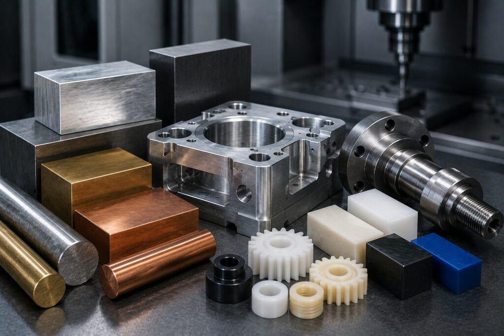
A Complete Guide to Choosing Materials for CNC Machined Components Choosing the right material is one of the most important decisions when designing a CNC machined part. Material selection affects strength, weight, durability, corrosion resistance, machinability, surface finish, cost, and overall product performance. Therefore, engineers should select a material based on the actual application rather than choosing a material simply because it is easy to machine or inexpensive. At Polymach365, we support CNC milling, CNC turning, 3-axis, 4-axis and 5-axis machining, prototype manufacturing, low-volume production, custom CNC parts, and precision machined components. Understanding the characteristics of different CNC machining materials can help you make better manufacturing decisions. Why Material Selection Matters in CNC Machining Every CNC machined component operates under different conditions. For example, an automotive component may require strength and wear resistance, while an electronic housing may prioritize lightweight construction and electrical insulation. Therefore, material selection should consider: Mechanical strength Hardness Weight Corrosion resistance Temperature resistance Wear resistance Chemical resistance Machinability Surface finish Material availability Manufacturing cost As a result, selecting the correct material can improve both part performance and manufacturing efficiency. Common CNC Machining Materials CNC machines can manufacture components from a wide range of metals and engineering plastics. Common CNC machining materials include: Metals Aluminum Stainless Steel Carbon Steel Alloy Steel Tool Steel Brass Copper Titanium Engineering Plastics ABS Nylon Delrin Polycarbonate PEEK PTFE Each material has different properties. Therefore, engineers should evaluate the material according to the requirements of the finished component. 1. Aluminum CNC Machining Aluminum is one of the most widely used materials for CNC machining. It offers a useful combination of low weight, good machinability, strength, and corrosion resistance. Advantages of Aluminum Lightweight Good machinability Good strength-to-weight ratio Corrosion resistance Suitable for complex machining Good surface finishing options Therefore, aluminum is commonly selected for: Automotive components Aerospace components Electronic housings Brackets Enclosures Fixtures Machine components Prototypes Moreover, aluminum can be an excellent choice when reducing component weight is important. 2. Stainless Steel CNC Machining Stainless steel provides strength, durability, and corrosion resistance. Therefore, it is suitable for components that operate in demanding environments. Common Applications Industrial equipment Medical components Food-processing equipment Automotive parts Machinery components Chemical-processing equipment Precision tooling However, stainless steel can require more cutting force than aluminum. Consequently, manufacturers need appropriate cutting tools and machining parameters to achieve efficient production and good surface quality. 3. Carbon Steel CNC Machining Carbon steel provides a combination of strength, durability, and cost efficiency. It can be used for: Machine components Shafts Brackets Fixtures Industrial equipment Structural components Therefore, carbon steel can be a practical choice when strength is important and the application does not require the corrosion resistance of stainless steel. 4. Tool Steel CNC Machining Tool steel is designed for applications requiring high hardness, strength, and wear resistance. It is commonly used for: Dies Tooling Mold components Cutting tools Fixtures Precision manufacturing components However, harder materials can increase machining difficulty. Therefore, manufacturers should select appropriate tooling and machining strategies when working with tool steels. 5. Brass CNC Machining Brass is known for its good machinability, corrosion resistance, and attractive appearance. Therefore, CNC-machined brass components are often used for: Fittings Bushings Connectors Valves Electrical components Decorative components Precision mechanical parts Moreover, brass can provide a good combination of machinability and functional performance. 6. Copper CNC Machining Copper provides excellent electrical and thermal conductivity. Therefore, it is commonly selected for components where heat or electrical conductivity is important. Applications include: Electrical components Heat-transfer components Connectors Busbars Specialized industrial components However, copper can present machining challenges because of its material characteristics. Consequently, tool selection and cutting parameters should be optimized for reliable results. 7. Titanium CNC Machining Titanium provides a high strength-to-weight ratio and excellent corrosion resistance. Therefore, it is commonly used in demanding applications such as: Aerospace Medical equipment High-performance engineering Chemical processing Specialized industrial components However, titanium can be more difficult to machine than many conventional materials. It can generate heat during cutting and place higher demands on cutting tools. As a result, titanium machining requires appropriate tooling, speeds, feeds, and cooling strategies. 8. ABS CNC Machining ABS is an engineering thermoplastic that combines relatively low weight with good impact resistance and machinability. Therefore, it can be useful for: Prototype housings Enclosures Consumer products Fixtures Product-development components Moreover, CNC machining ABS can provide functional prototypes without requiring injection molding tooling. 9. Nylon CNC Machining Nylon is a lightweight engineering plastic with good wear resistance and low friction characteristics. Therefore, it can be useful for: Bushings Rollers Gears Guides Spacers Mechanical components However, plastics can respond differently to heat and machining forces than metals. Consequently, manufacturers should consider thermal effects and workholding when machining nylon. 10. Delrin CNC Machining Delrin, also known as acetal, is widely used for precision plastic components. It provides: Good dimensional stability Low friction Good machinability Wear resistance Low moisture absorption compared with many other plastics Therefore, Delrin is suitable for: Bushings Gears Rollers Fixtures Mechanical components Precision plastic parts 11. PEEK CNC Machining PEEK is a high-performance engineering plastic used when components require demanding mechanical and thermal performance. Therefore, PEEK may be selected for specialized applications involving: High temperatures Chemical exposure Wear Mechanical loading Electrical insulation However, PEEK can be significantly more expensive than common engineering plastics. Consequently, it should generally be selected when its performance characteristics justify the additional material cost. Metal vs Plastic for CNC Machining One of the first decisions engineers often make is whether to manufacture a component from metal or plastic. Choose Metal When You Need: Higher mechanical strength Greater rigidity Higher temperature capability Improved wear resistance Long-term structural performance Choose Engineering Plastic When You Need: Lower weight Electrical insulation Reduced friction Corrosion resistance Lower component weight Specialized chemical resistance Therefore, the correct choice depends on the operating conditions of the component. How Machinability Affects Material Selection Machinability describes how easily a material can be cut and processed. Materials with good machinability can often provide: Faster machining Longer tool life Better surface finish Lower
What Factors Affect CNC Machining Accuracy?
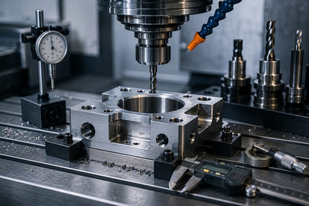
Understanding the Key Factors That Influence CNC Part Accuracy CNC machining is widely used to manufacture precision components for automotive, aerospace, medical, robotics, tooling, and industrial applications. However, achieving accurate CNC machined parts depends on more than simply using a modern CNC machine. Several factors can influence the final accuracy of a component, including machine condition, tooling, material, workholding, machining parameters, temperature, part design, programming, and inspection methods. Therefore, manufacturers must control the entire machining process to achieve consistent and reliable results. At Polymach365, we provide CNC milling, CNC turning, 3-axis, 4-axis, and 5-axis machining, prototype manufacturing, low-volume production, custom CNC parts, and precision machining solutions. Understanding the factors that affect CNC accuracy can help engineers prepare better designs and achieve more consistent manufacturing results. What Is CNC Machining Accuracy? CNC machining accuracy refers to how closely the finished component matches the dimensions and geometry specified in the original CAD model or engineering drawing. For example, if a drawing specifies a hole diameter of 20 mm, the finished hole must remain within the specified tolerance range. Accuracy can involve: Dimensional accuracy Positional accuracy Geometric accuracy Hole location Flatness Parallelism Perpendicularity Roundness Surface finish Therefore, CNC accuracy is not limited to one measurement. It involves the overall dimensional and geometric quality of the finished component. 1. CNC Machine Condition The condition of the CNC machine is one of the most important factors affecting machining accuracy. Over time, machine components can experience wear. Bearings, guideways, ball screws, spindles, and other mechanical components can gradually affect positioning and cutting performance. Common machine-related issues include: Backlash Spindle runout Guideway wear Positioning errors Vibration Poor machine alignment Therefore, regular maintenance, calibration, and machine inspection are essential for maintaining consistent accuracy. 2. Tool Wear Cutting tools gradually wear as they remove material from the workpiece. As tool wear increases, manufacturers may experience: Dimensional variation Poor surface finish Increased cutting forces Higher temperatures Burr formation Tool breakage For example, a worn cutting tool may remove slightly less material than a new tool. Consequently, the finished feature may gradually move outside the required tolerance. How to Control Tool Wear Manufacturers can improve accuracy by: Monitoring tool condition Using suitable cutting tools Setting appropriate cutting parameters Replacing worn tools Using tool-life monitoring systems As a result, proper tool management helps maintain consistent dimensions throughout production. 3. Cutting Parameters CNC machining parameters directly influence cutting forces, heat generation, tool life, and surface quality. Important parameters include: Spindle speed Feed rate Depth of cut Stepover Cutting speed Tool engagement Incorrect parameters can create excessive vibration or heat. Therefore, machining parameters should be selected according to the material, cutting tool, machine capability, and component geometry. Optimizing these parameters can improve both accuracy and production efficiency. 4. Workholding and Fixturing A workpiece must remain securely positioned during machining. If the component moves, vibrates, or deforms during cutting, its final dimensions may not meet the required specifications. Workholding problems can cause: Part movement Vibration Positioning errors Distortion Inconsistent dimensions Therefore, manufacturers should select fixtures that provide sufficient support without applying excessive clamping force. This becomes particularly important when machining thin walls, flexible materials, or complex components. 5. Material Properties Different materials behave differently during CNC machining. For example, aluminum, stainless steel, titanium, plastics, and hardened steels have different: Hardness Thermal expansion Cutting characteristics Elasticity Heat conductivity Internal stresses Therefore, material properties can directly influence machining accuracy. Some materials may deform when excessive cutting forces are applied, while others may generate significant heat during machining. Consequently, machining parameters and tooling should be adapted to the selected material. 6. Thermal Expansion Heat is naturally generated during CNC machining. The cutting tool, workpiece, spindle, and machine components can all experience temperature changes. When materials expand or contract because of temperature changes, dimensional accuracy can be affected. This becomes particularly important when manufacturing components with tight tolerances. How to Reduce Thermal Effects Manufacturers can: Control cutting parameters Use appropriate coolant Maintain stable machine temperatures Allow components to reach suitable inspection temperatures Avoid unnecessarily aggressive machining Therefore, thermal management is an important part of precision CNC machining. 7. Tool Deflection Cutting tools can bend slightly when subjected to machining forces. Tool deflection becomes more significant when: Tool overhang is excessive Cutting forces are high The tool diameter is small Deep cavities are being machined Hard materials are being cut As a result, the tool may not follow the intended toolpath exactly. How to Reduce Tool Deflection Manufacturers can: Minimize tool overhang Use more rigid tooling Reduce cutting forces Select an appropriate tool diameter Optimize cutting parameters Consequently, rigid tool setups can improve dimensional accuracy and surface finish. 8. Workpiece Deformation Some components can deform during machining because of cutting forces or internal material stresses. This is especially common with: Thin walls Thin plates Long components Flexible materials Large components Therefore, the machining strategy should account for the component’s structural characteristics. Using lighter cutting passes and suitable workholding can help reduce deformation. 9. Machine Vibration Vibration can significantly affect CNC machining accuracy. Excessive vibration can produce: Chatter marks Poor surface finish Dimensional variation Tool wear Tool breakage Common sources include: Poor workholding Excessive tool overhang Incorrect cutting parameters Machine instability Improper tooling Therefore, reducing vibration is essential when producing precision components. 10. CNC Programming and Toolpath Accuracy The CNC machine follows programmed toolpaths to manufacture the component. Programming errors can therefore affect the final part. Potential problems include: Incorrect tool offsets Wrong work coordinates Incorrect tool diameter compensation Incorrect machining sequence Programming mistakes Before production, manufacturers should verify the toolpath and machining strategy. Furthermore, simulation can help identify potential collisions and programming problems before the machine begins cutting. As a result, accurate programming contributes directly to accurate CNC machining. 11. Part Design and Geometry The design of the component itself can affect how accurately it can be machined. Features such as: Very thin walls Deep pockets Small internal radii Narrow slots Difficult-to-access surfaces Complex internal geometries may require specialized tools or additional machining setups. Therefore, engineers should consider Design
Common CNC Machining Defects and How to Prevent Them
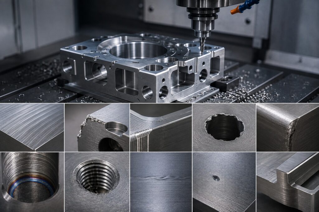
A Practical Guide to Improving CNC Machined Part Quality CNC machining delivers accurate and repeatable components for industries such as automotive, aerospace, medical, robotics, tooling, and industrial manufacturing. However, even advanced CNC equipment can produce defects when machining parameters, tooling, workholding, programming, or material conditions are not properly controlled. Common CNC machining defects can affect dimensional accuracy, surface finish, part geometry, assembly, and overall product performance. Therefore, identifying the cause of a defect early can help manufacturers reduce scrap, rework, production delays, and unnecessary costs. At Polymach365, we provide CNC milling, CNC turning, 3-axis, 4-axis and 5-axis machining, prototype manufacturing, low-volume production, custom CNC parts, and precision machining solutions. Understanding common machining problems can help engineers design and manufacture better components. What Are CNC Machining Defects? CNC machining defects are unwanted variations or imperfections that occur during the manufacturing process. They may result from: Incorrect cutting parameters Tool wear Improper workholding Machine vibration Material characteristics Programming errors Poor tool selection Excessive heat Incorrect tolerances Inadequate inspection Therefore, CNC quality control requires manufacturers to consider the complete machining process rather than focusing only on the finished component. 1. Poor Surface Finish Poor surface finish is one of the most common CNC machining defects. A machined surface may show: Visible tool marks Roughness Scratches Chatter patterns Uneven surfaces Common Causes Poor surface finish can result from: Worn cutting tools Incorrect feed rate Incorrect spindle speed Excessive cutting depth Machine vibration Poor workholding Incorrect tool geometry How to Prevent It Manufacturers can improve surface finish by: Using sharp and suitable cutting tools Optimizing cutting parameters Reducing vibration Improving workholding Selecting the appropriate toolpath Using suitable finishing passes Consequently, proper process control can produce smoother and more consistent machined surfaces. 2. Dimensional Inaccuracy Dimensional errors occur when the finished component does not meet the specified dimensions. For example, a hole may be too large, a shaft may be undersized, or a pocket may be deeper than required. Common Causes Tool wear Machine calibration issues Thermal expansion Incorrect tool offsets Programming errors Material movement Improper workholding How to Prevent It Manufacturers can reduce dimensional errors by: Checking machine calibration Verifying tool offsets Monitoring tool wear Controlling machining temperature Inspecting critical dimensions Using appropriate cutting parameters Therefore, regular measurement during production can help identify dimensional changes before they result in multiple defective parts. 3. Chatter and Vibration Chatter appears as unwanted vibration between the cutting tool, machine, workpiece, or fixture. It can produce visible marks and reduce surface quality. Common Causes Excessive cutting speed Long tool overhang Weak workholding Incorrect cutting parameters Poor machine rigidity Large cutting forces How to Prevent CNC Chatter Manufacturers can reduce chatter by: Shortening tool overhang Improving workholding Adjusting spindle speed Reducing cutting depth Using appropriate tooling Optimizing toolpaths Furthermore, selecting a more rigid setup can significantly improve machining stability. 4. Tool Wear Cutting tools gradually wear as they remove material. As tool wear increases, manufacturers may experience: Dimensional variation Poor surface finish Increased cutting forces Higher temperatures Tool breakage Reduced productivity How to Prevent Tool Wear Manufacturers should: Select the correct cutting tool Use appropriate cutting parameters Monitor tool condition Use suitable coolant or lubrication when required Replace tools at appropriate intervals Therefore, proactive tool monitoring can help maintain consistent part quality. 5. Burr Formation Burrs are small unwanted pieces of material that remain along machined edges. They commonly occur around: Holes Slots External edges Intersections Milled pockets Common Causes Burr formation can be influenced by: Tool condition Cutting direction Material properties Cutting parameters Tool geometry How to Prevent Burrs Manufacturers can reduce burrs through: Proper tool selection Optimized cutting conditions Appropriate cutting direction Edge-break specifications Deburring operations Consequently, including practical edge-break requirements in the design can simplify finishing. 6. Tool Breakage Tool breakage can cause serious production problems. A broken cutting tool can damage the workpiece, interrupt production, and potentially affect the machine. Common Causes Excessive cutting forces Incorrect feeds and speeds Excessive tool engagement Long tool overhang Poor workholding Incorrect tool selection Hard or difficult-to-machine materials Prevention To reduce tool breakage: Use appropriate tooling Optimize cutting parameters Minimize tool overhang Maintain secure workholding Monitor cutting conditions Use suitable machining strategies Therefore, matching the tool to the material and geometry is essential. 7. Thermal Deformation Heat is generated during CNC machining, particularly during aggressive cutting operations. Excessive heat can cause the workpiece or machine components to expand. As a result, the component may move outside the required dimensional tolerance. How to Prevent Thermal Problems Manufacturers can: Control cutting parameters Use appropriate coolant Allow suitable cooling time Monitor machining temperatures Avoid unnecessarily aggressive cutting This becomes especially important when manufacturing components with tight tolerances. 8. Incorrect Hole Dimensions or Positions Holes are critical features in many CNC machined components. Problems may include: Incorrect hole diameter Incorrect hole depth Misaligned holes Incorrect hole position Poor surface quality Common Causes Incorrect tool selection Tool deflection Machine positioning errors Improper workholding Tool wear Programming mistakes Prevention Manufacturers can improve hole accuracy by: Using suitable drilling tools Checking tool offsets Using reaming or boring when required Verifying hole locations Inspecting critical features Therefore, hole requirements should be clearly specified in the CAD model or engineering drawing. 9. Warping and Part Deformation Thin or flexible components can deform during machining. This is particularly important when machining: Thin walls Long components Thin plates Flexible materials Components with uneven material removal Common Causes Excessive cutting forces Poor workholding Internal material stresses Excessive heat Improper machining sequence How to Prevent Deformation Manufacturers can: Improve workholding Use lighter cutting passes Optimize machining sequences Maintain adequate wall thickness Remove material gradually Consequently, proper part design and machining strategy can reduce deformation. 10. Incorrect Surface Geometry Sometimes a component may meet its basic dimensions but still have problems with flatness, parallelism, perpendicularity, or other geometric characteristics. For example, two surfaces may have the correct dimensions but fail to remain parallel. Common Causes Poor machine setup Workpiece movement Tool deflection Thermal effects Incorrect machining sequence Inadequate inspection Prevention Manufacturers can improve